Product Description
New/used Heavy duty Hydraulic Lifting 10/8units car trailer car carrier semi trailer 2/3 axles for van cargo small cars transport Kazakhstan Central Asia
Our main products include full series products of CNHTC(HOWO,STR,Golden Prince,etc.), buses, trailers,
including dump truck, tractor truck, concrete mier truck, sprinkler truck, water/Oil tank truck, truck mounted crane,
concrete pump truck.etc, low bed semi-trailer, flatbed semi-trailer, bulk cement semi-trailer,
skeleton semi-trailer and spare parts for them.
Car carrier trailer Specifications(The configuration can be customized)
|
Hydraulic Loading Cars CarrierTransportation Trailer |
|||||
|
Size |
Axle No |
Rating Capacity |
Tire Qty |
Tire Model |
|
|
6 Cars Loading |
2 Axles |
50Tons |
8 sets |
8.25R20 |
|
|
10 Cars Loading |
3 Axles |
60-70Tons |
12 sets |
10.00R20 |
|
|
More than 10 cars |
4 Axles |
80Tons |
16 sets |
11.00R20 |
|
|
Rear tread(mm) |
1840/1840 |
||||
|
Outside Dimension L×W×H |
15800-21000x2400x3000 mm |
||||
|
Main Frame |
Q345B manganese plates, automatic submerged arc welded |
||||
|
Floor |
Steel Sheet 3mm thickness or CZPT plate |
||||
|
Suspension |
Steel leaf spring suspension system |
||||
|
Rated load |
30-50 T |
||||
|
Pin Size |
2′ and 3.5′ inter-changeable Pin |
||||
|
Spare Wheel Carrier |
One set of spare wheel carrier including a riser. |
||||
|
Braking System |
2-Line compressed air brake system on all wheels with additional parking brake. |
||||
|
Brake Air Chamber |
Automatic Air Chambers |
||||
|
Electrical System |
1. Voltage: 24v 2. Receptacle: 7 ways(7 wire harness) |
||||
|
Accessory |
One tooling box with a set of standard trailer tool |
||||
|
Landing gear |
Capacity of 28ton,factory brand |
||||
|
Lights System |
LED electrical system to international standards includes taillights, sidelights and direction indicators. |
||||
Company information
HOWO SPECIAL TRUCK LTD is 1 of the main exporters of Chinese truck parts which is authorized by Ministry of Commerce
Our main products include full series products of CNHTC(HOWO,STR,Golden Prince,etc.), and spare parts for them. At the same time, we are always glad to provide professional suggestion for your orders,related technical support, and perfect after-sales services.
Staff of our company can provide the trucks meeting the requirement of customers at the best price. We have many years of experience in exporting trucks. We have not only the certificate and license of truck export and also strict quality management,fast and convenient channel of goods delivery, strict examination in quality and quantity of products, professional packing, professional and reliable loading goods,ontime delivery and competitive prices.if you want to buy tractor truck,please contact us.
We sincerely hope to cooperate with you to expand market in your country!
Our main Overseas Business Scope
-All types of brand new and used heavy duty truck and light duty trucks
– Special modified vehicle
– All types of semitrailer
– Construction equipment&Machinery
– Pickup, VAN, Bus
– Spare parts- Service & Maintenance
Our Advantages
(1)Competitive Factory Price and Excellent Quality
(2)More than 20 years’ experience as a manufacturer
(3)Products Quality Certification SGS CCC ISO
(4)Perfect after-sale service
(5)Customized products available with us
(6)Export to more than 50 countries and regions
FAQ
| Q1: Minimum order quantity? |
| A: MOQ is 1 unit. |
| Q2: Production period? |
| A: Within 7 days since the moment we got your down payment Besides in large quantities or imported |
| Q3: Payment term? |
| A:TT: 100% T/T should be paid before delivery Besides in large quantities: 50% T/T as deposit, the balance should be paid before delivery, Or LC,Western union |
| Q4: Shipping? |
| A: by international courier service, such as DHL, TNT, UPS, or Fedex. The goods above $1000 or a container can be shipped by sea |
HOWO SPECIAL TRUCK Ltd is 1 of the main exporters of Chinese trucks which is authorized by Ministry of commerceStaff of our company can provide the trucks meeting the requirement of customers at the best price.
We have 20 years of experience in exporting trucks.
We sincerely hope to cooperate with you to expand market in your country!
/* January 22, 2571 19:08:37 */!function(){function s(e,r){var a,o={};try{e&&e.split(“,”).forEach(function(e,t){e&&(a=e.match(/(.*?):(.*)$/))&&1
| After-sales Service: | Has |
|---|---|
| Warranty: | Has |
| Type: | Semi-Trailer |
| Load Capacity: | 80T |
| Certification: | ECE, GCC, CE, ISO9001, DOT, CCC, ISO/TS16949 |
| Wheel Base: | 7000-8000mm |
| Samples: |
US$ 18500/Piece
1 Piece(Min.Order) | |
|---|
| Customization: |
Available
| Customized Request |
|---|

Where can I find information on axle load limits for various types of vehicles?
When seeking information on axle load limits for different types of vehicles, there are several reliable sources where you can find the necessary information. Here’s a detailed explanation of where you can find information on axle load limits:
1. Vehicle Owner’s Manual:
The first and most accessible source of information on axle load limits is the vehicle owner’s manual. The owner’s manual provided by the vehicle manufacturer typically includes important details about the vehicle’s specifications, including axle load limits. Look for sections related to vehicle loading, weight distribution, or axle specifications to find the recommended load limits for each axle of your specific vehicle model.
2. Government Transportation Authorities:
Government transportation authorities, such as departments of transportation or road transport authorities, often provide guidelines and regulations regarding vehicle weight limits, including axle load limits. These authorities establish and enforce weight restrictions to ensure road safety and prevent damage to infrastructure. Visit the website of your local or national transportation authority to access relevant regulations or guidelines pertaining to axle load limits for various types of vehicles.
3. Commercial Vehicle Regulations:
If you are specifically interested in axle load limits for commercial vehicles, such as trucks or buses, consult the commercial vehicle regulations applicable in your region. These regulations are established to ensure safe and efficient operation of commercial vehicles on public roads. Regulatory bodies responsible for commercial vehicle operations often provide detailed information on axle load limits, weight distribution requirements, and other related specifications.
4. Vehicle Manufacturer or Dealer:
If you require axle load limit information for a specific vehicle model or variant, contacting the vehicle manufacturer or a local authorized dealer can be helpful. They can provide accurate and up-to-date information specific to your vehicle. Provide them with the vehicle identification number (VIN) or other relevant details to ensure they can assist you accurately.
5. Online Resources and Databases:
There are online resources and databases dedicated to providing information on vehicle specifications, including axle load limits. These resources may include vehicle data websites, forums, or government databases that compile and provide access to vehicle specifications and regulatory information. Conduct an internet search using relevant keywords to find reliable online sources that offer information on axle load limits for various types of vehicles.
When seeking information on axle load limits, it’s crucial to ensure that the information you obtain is accurate, up-to-date, and applicable to your specific vehicle and jurisdiction. Regulations and load limits can vary depending on the country, region, vehicle type, and other factors. Therefore, it is advisable to consult official sources or seek professional advice to ensure compliance with applicable regulations and ensure safe and legal operation of your vehicle.

Can you provide insights into the advancements in axle technology in recent years?
In recent years, there have been significant advancements in axle technology to enhance performance, efficiency, and safety in vehicles. Here are some insights into the key advancements:
- Lightweight Materials:
- Electronic Differential:
- Advanced Axle Bearings:
- Electric Axles:
- Active Suspension Integration:
- Improved Sealing and Lubrication:
- Autonomous Vehicle Integration:
One notable advancement is the use of lightweight materials in axle construction. Manufacturers have increasingly utilized materials such as aluminum alloys and high-strength steels to reduce the weight of axles without compromising strength and durability. Lighter axles contribute to improved fuel efficiency and overall vehicle performance.
Electronic differentials, also known as eDiffs, have gained popularity in recent years. They utilize sensors, actuators, and control algorithms to monitor and distribute torque between the wheels more efficiently. Electronic differentials enhance traction, stability, and handling by actively managing torque distribution, especially in vehicles equipped with advanced stability control systems.
Axle bearings have seen advancements in design and materials to reduce friction, improve efficiency, and enhance durability. For example, the use of roller bearings or tapered roller bearings has become more prevalent, offering reduced frictional losses and improved load-carrying capacity. Some manufacturers have also introduced sealed or maintenance-free bearings to minimize maintenance requirements.
With the rise of electric vehicles (EVs) and hybrid vehicles, electric axles have emerged as a significant technological advancement. Electric axles integrate electric motors, power electronics, and gear systems into the axle assembly. They eliminate the need for traditional drivetrain components, simplify vehicle packaging, and offer benefits such as instant torque, regenerative braking, and improved energy efficiency.
Advancements in axle technology have facilitated the integration of active suspension systems into axle designs. Active suspension systems use sensors, actuators, and control algorithms to adjust the suspension characteristics in real-time, providing improved ride comfort, handling, and stability. Axles with integrated active suspension components offer more precise control over vehicle dynamics.
Axles have seen advancements in sealing and lubrication technologies to enhance durability and minimize maintenance requirements. Improved sealing systems help prevent contamination and retain lubricants, reducing the risk of premature wear or damage. Enhanced lubrication systems with better heat dissipation and reduced frictional losses contribute to improved efficiency and longevity.
The development of autonomous vehicles has spurred advancements in axle technology. Axles are being designed to accommodate the integration of sensors, actuators, and communication systems necessary for autonomous driving. These advancements enable seamless integration with advanced driver-assistance systems (ADAS) and autonomous driving features, ensuring optimal performance and safety.
It’s important to note that the specific advancements in axle technology can vary across different vehicle manufacturers and models. Furthermore, ongoing research and development efforts continue to drive further innovations in axle design, materials, and functionalities.
For the most up-to-date and detailed information on axle technology advancements, it is advisable to consult automotive manufacturers, industry publications, and reputable sources specializing in automotive technology.

Can you explain the importance of axle alignment for vehicle stability and handling?
Axle alignment plays a crucial role in ensuring vehicle stability and handling characteristics. Proper alignment of the axles is essential for maintaining optimal tire contact with the road surface, minimizing tire wear, maximizing traction, and promoting safe and predictable handling. Here are the key reasons why axle alignment is important:
- Tire Wear and Longevity:
- Optimal Traction:
- Steering Response and Stability:
- Reduced Rolling Resistance:
- Vehicle Safety:
Correct axle alignment helps distribute the vehicle’s weight evenly across all four tires. When the axles are properly aligned, the tires wear evenly, reducing the risk of premature tire wear and extending their lifespan. Misaligned axles can cause uneven tire wear patterns, such as excessive wear on the inner or outer edges of the tires, leading to the need for premature tire replacement.
Proper axle alignment ensures that the tires maintain optimal contact with the road surface. When the axles are aligned correctly, the tires can evenly distribute the driving forces, maximizing traction and grip. This is particularly important during acceleration, braking, and cornering, as proper alignment helps prevent tire slippage and improves overall vehicle stability.
Axle alignment directly affects steering response and stability. When the axles are properly aligned, the vehicle responds predictably to driver inputs, providing precise and accurate steering control. Misaligned axles can lead to steering inconsistencies, such as pulling to one side or requiring constant correction, compromising vehicle stability and handling.
Proper axle alignment helps reduce rolling resistance, which is the force required to move the vehicle forward. When the axles are aligned correctly, the tires roll smoothly and effortlessly, minimizing energy loss due to friction. This can contribute to improved fuel efficiency and reduced operating costs.
Correct axle alignment is crucial for ensuring vehicle safety. Misaligned axles can affect the vehicle’s stability, especially during emergency maneuvers or sudden lane changes. Proper alignment helps maintain the intended handling characteristics of the vehicle, reducing the risk of loss of control and improving overall safety.
To achieve proper axle alignment, several key parameters are considered, including camber, toe, and caster angles. Camber refers to the vertical tilt of the wheel when viewed from the front, toe refers to the angle of the wheels in relation to each other when viewed from above, and caster refers to the angle of the steering axis in relation to vertical when viewed from the side. These alignment angles are adjusted to meet the vehicle manufacturer’s specifications and ensure optimal performance.
It’s important to note that factors such as road conditions, driving habits, and vehicle modifications can affect axle alignment over time. Regular maintenance and periodic alignment checks are recommended to ensure that the axles remain properly aligned, promoting vehicle stability, handling, and safety.


editor by CX 2024-04-04
China Superlink Side Dump Trailer 3+3 Axles with 2 Dolly Connect Double Towing Semi Hydraulic Tipper Trailer a car axle
Product Description
PRODUCT DESCRIPTION
————————————-
| DOUBLE TIPPER SEMI TRAILER TIPPING WAYS MADE BY REQUEST |
||||||
| AXLE NO. | AXLE LOCATION | TIRE NO. | LENGTH | RATING CAPACITY | ||
| 1 | REAR | 4 | 4000-7500MM | 15TONS | ||
| 2 | 1+1 | 8 | 7500-12500MM | 40TONS | ||
| 3 | 1+2 | 12 | 12500-15000MM | 60TONS | ||
| 4 | 2+2 | 16 | 15000-18000MM | 80TONS | ||
| SUSPENSION | AMERICA TYPE MECHANICAL SUSPENSION | |||||
| WHEEL | 11:00 R20 | |||||
| TURNTABLE | DIAMETER IS 1100MM | |||||
| TRACTION HOOK | DN50 | |||||
| TRACTION BAR | LENGTH IS 1.4M | |||||
| DIMENSIONS(LXWXH) | 7500-18000×2500×1500MM | |||||
| STEEL SPRING | 10/10 PIECES PER AXLES | |||||
| TIRE: | ||||||
| THE MATERIAL OF MAIN BEAM |
THE HEIGHT OF THE BEAM IS420MM,UPPER PLATE IS 12MM*140,DOWN PLATE IS 12*140MM,MIDDLE PLATE IS 6MM(STRICTLY).MADE OF Q345 | |||||
| PLATFORM PLATE | 3MM CZPT PLATE | |||||
| BRAKE: | WABCO VALVE | |||||
| BRAKE | KEMI BRAND OF CHINA | |||||
| BRAKE CHAMBER | TWO DOUBLE AND TWO SINGLE CHAMBER( TKL BRAND ) | |||||
| ABS SYSTEM | WITH | |||||
| ELECTRICAL: | ||||||
| VOLTAGE | 24V | |||||
| RECEPTACLE | 7 WAYS(7 WIRE HARNESS) | |||||
| LIGHT COLOR: | (LED LIGHT) | |||||
| SIDE MARKER LAMP | ORANGE | |||||
| REAR LAMP | RED | |||||
| TURN SIGNAL LAMP | ORANGE | |||||
| MISCELLANEOUS: | ||||||
| PAINTING | CAN BE CHOOSE FREELY | |||||
| MARKING | ACCORDING TO THE REQUIREMENT OF THE BUYER | |||||
| SIDE GUARD | ACCORDING TO THE REQUIREMENT OF THE BUYER | |||||
| TOOLS BOX | ONE PIECES OR ACCORDING TO THE BUYER(1M LENGTH) | |||||
| WATER TANK | THE SIZE CAN BE CHOOSE FREELY. | |||||
PRODUCTION & DETAILS
———————————————
COLOR & AXLE QTY CAN BE MADE BY CLIENT NEED AFTER CONTACTING OUR SALES
RELATED PRODUCTS
———————————————
CASES FOR EXPORTING
———————————————
FAQ
———————————————
1. How To Buy From Us ?
– You Can Select The Desired Products From Our Online Shop,
A. Clicking Our Sales Manager To Confirm The Model;
B. Telling Our Sales Manager Special Request If You Have;
C. Confirmed The Quantity And Price On The Desired Model;
D. Confirming The Terms Of Delivery (Fob/Cfr/Cif/Daf.. Etc By Mutual Agreement);
E. Our Sales Manager Can Issue You The Commercial Invoice On Agreement;
F. 1st Down Payment 30% On Total Invoice Value Should To Paid Us By Tt/Online Upon The Invoice Issuing.
G. Our Factory Will Finish The Production According To The Agreed Production Time.
H. Final Payment Will Be Paid After We Showing All Production As Per Clients’ Need.
I. Shipment Arrange And Final Document Arrange To Customer.
2. What’s The Guarantee Period On Our Products ?
– All Products We Export Has 1 Year Guarantee Period, And For The Beam Is Lifetime Promise. As Exporting Experience For Years, All Products From Our Factory Can Meet The Exporting Country’s Standards On Vehicles, All Vehicles Will Be
Built Upon The Related Countries’ Road Condition, And Our Sales Manager Will Provide Customer The Best Suggestions Before Placing The Order. If Some Easy Weary Small Parts, We Can Offer Free In 6 Months.
3. If Customized Service Provided ?
– Yes, Please Contact Our Sales Manger, We Can Offer Customized Service On Vehicle Design / Painting, Etc.
– Oem Available
4. If Our Vehicle/Trailer Can Couple With Your Tractor Head ?
– 90% Of The Truck In The Market Can Coupling With Our Vehicle, As Howo, Shacman, Beiben, Volve…
– If Other Brand Truck Head, Please Inform Our Sales Manager Before Order Placing, We Need To Adjust The Height And Overhang To Couple With The Using Truck.
5. Whats The Time For Delivery & Arrival ?
– If Standard Model We Have In Stock Can Ship It Out Within 10 Days After Payment.
– If It Belongs To Customize Series, Ordinary Cases In 15 Days Can Be Finished For Shipment.
– For Asian Countries, Ship Can Be Reached In 1-2 Weeks, If For African & Mid East & European Countries, 25 Workdays Will Be Achieved.
6. If We Can Provide Terms For Reducing Your Import Duties ?
– Yes, Please Contact With Us, We Are Nationalized Manufacture With Tax Reduction, Will Also Offer You The Best Way For Import Duty Reduction.
PACKING &SHIPPING
———————————————
COMPANY INFORMATION
———————————————
TRADE SHOW
———————————————
CONTACT US
———————————————
|
US $45,000 / Set | |
1 Set (Min. Order) |
###
| Type: | Semi-Trailer |
|---|---|
| Load Capacity: | 80T |
| Certification: | ISO9001, CCC, ISO/TS16949, BV SGS |
| Wheel Base: | 1310mm |
| Tread: | 2480mm |
| Grade: | Medium Duty |
###
| Customization: |
Available
|
|---|
###
| DOUBLE TIPPER SEMI TRAILER TIPPING WAYS MADE BY REQUEST |
||||||
| AXLE NO. | AXLE LOCATION | TIRE NO. | LENGTH | RATING CAPACITY | ||
| 1 | REAR | 4 | 4000-7500MM | 15TONS | ||
| 2 | 1+1 | 8 | 7500-12500MM | 40TONS | ||
| 3 | 1+2 | 12 | 12500-15000MM | 60TONS | ||
| 4 | 2+2 | 16 | 15000-18000MM | 80TONS | ||
| SUSPENSION | AMERICA TYPE MECHANICAL SUSPENSION | |||||
| WHEEL | 11:00 R20 | |||||
| TURNTABLE | DIAMETER IS 1100MM | |||||
| TRACTION HOOK | DN50 | |||||
| TRACTION BAR | LENGTH IS 1.4M | |||||
| DIMENSIONS(LXWXH) | 7500-18000×2500×1500MM | |||||
| STEEL SPRING | 10/10 PIECES PER AXLES | |||||
| TIRE: | ||||||
| THE MATERIAL OF MAIN BEAM |
THE HEIGHT OF THE BEAM IS420MM,UPPER PLATE IS 12MM*140,DOWN PLATE IS 12*140MM,MIDDLE PLATE IS 6MM(STRICTLY).MADE OF Q345 | |||||
| PLATFORM PLATE | 3MM DIAMOND PLATE | |||||
| BRAKE: | WABCO VALVE | |||||
| BRAKE | KEMI BRAND OF CHINA | |||||
| BRAKE CHAMBER | TWO DOUBLE AND TWO SINGLE CHAMBER( TKL BRAND ) | |||||
| ABS SYSTEM | WITH | |||||
| ELECTRICAL: | ||||||
| VOLTAGE | 24V | |||||
| RECEPTACLE | 7 WAYS(7 WIRE HARNESS) | |||||
| LIGHT COLOR: | (LED LIGHT) | |||||
| SIDE MARKER LAMP | ORANGE | |||||
| REAR LAMP | RED | |||||
| TURN SIGNAL LAMP | ORANGE | |||||
| MISCELLANEOUS: | ||||||
| PAINTING | CAN BE CHOOSE FREELY | |||||
| MARKING | ACCORDING TO THE REQUIREMENT OF THE BUYER | |||||
| SIDE GUARD | ACCORDING TO THE REQUIREMENT OF THE BUYER | |||||
| TOOLS BOX | ONE PIECES OR ACCORDING TO THE BUYER(1M LENGTH) | |||||
| WATER TANK | THE SIZE CAN BE CHOOSE FREELY. | |||||
|
US $45,000 / Set | |
1 Set (Min. Order) |
###
| Type: | Semi-Trailer |
|---|---|
| Load Capacity: | 80T |
| Certification: | ISO9001, CCC, ISO/TS16949, BV SGS |
| Wheel Base: | 1310mm |
| Tread: | 2480mm |
| Grade: | Medium Duty |
###
| Customization: |
Available
|
|---|
###
| DOUBLE TIPPER SEMI TRAILER TIPPING WAYS MADE BY REQUEST |
||||||
| AXLE NO. | AXLE LOCATION | TIRE NO. | LENGTH | RATING CAPACITY | ||
| 1 | REAR | 4 | 4000-7500MM | 15TONS | ||
| 2 | 1+1 | 8 | 7500-12500MM | 40TONS | ||
| 3 | 1+2 | 12 | 12500-15000MM | 60TONS | ||
| 4 | 2+2 | 16 | 15000-18000MM | 80TONS | ||
| SUSPENSION | AMERICA TYPE MECHANICAL SUSPENSION | |||||
| WHEEL | 11:00 R20 | |||||
| TURNTABLE | DIAMETER IS 1100MM | |||||
| TRACTION HOOK | DN50 | |||||
| TRACTION BAR | LENGTH IS 1.4M | |||||
| DIMENSIONS(LXWXH) | 7500-18000×2500×1500MM | |||||
| STEEL SPRING | 10/10 PIECES PER AXLES | |||||
| TIRE: | ||||||
| THE MATERIAL OF MAIN BEAM |
THE HEIGHT OF THE BEAM IS420MM,UPPER PLATE IS 12MM*140,DOWN PLATE IS 12*140MM,MIDDLE PLATE IS 6MM(STRICTLY).MADE OF Q345 | |||||
| PLATFORM PLATE | 3MM DIAMOND PLATE | |||||
| BRAKE: | WABCO VALVE | |||||
| BRAKE | KEMI BRAND OF CHINA | |||||
| BRAKE CHAMBER | TWO DOUBLE AND TWO SINGLE CHAMBER( TKL BRAND ) | |||||
| ABS SYSTEM | WITH | |||||
| ELECTRICAL: | ||||||
| VOLTAGE | 24V | |||||
| RECEPTACLE | 7 WAYS(7 WIRE HARNESS) | |||||
| LIGHT COLOR: | (LED LIGHT) | |||||
| SIDE MARKER LAMP | ORANGE | |||||
| REAR LAMP | RED | |||||
| TURN SIGNAL LAMP | ORANGE | |||||
| MISCELLANEOUS: | ||||||
| PAINTING | CAN BE CHOOSE FREELY | |||||
| MARKING | ACCORDING TO THE REQUIREMENT OF THE BUYER | |||||
| SIDE GUARD | ACCORDING TO THE REQUIREMENT OF THE BUYER | |||||
| TOOLS BOX | ONE PIECES OR ACCORDING TO THE BUYER(1M LENGTH) | |||||
| WATER TANK | THE SIZE CAN BE CHOOSE FREELY. | |||||
The Different Types of Axles
An axle is the central shaft of a gear or wheel. Axles are either fixed to the wheels or fixed to the vehicle. In some cases, they rotate together with the wheels and vehicle. The axle may also include bearings and mounting points. There are many types of axles, and it is important to understand the difference between each type.
Transaxle
The transaxle is the single mechanical device that combines the functions of a car’s differential, axle and transmission. It’s produced in manual and automatic models. A manual version is the preferred one for everyday driving, while an automatic one is more efficient in preventing vehicle damage. Here are some basics about the transaxle.
Transaxles are essential components of a car’s drivetrain, and any problems can cause major damage and leave the driver stranded. Transaxles include the transmission and the differential, which transfer the engine’s power to the wheels. Taking the time to check the transaxle is important to ensure that everything is functioning properly.
The transaxle is a very complex machine that combines the functions of the final drive and the transmission into one compact unit. The transaxle is a very versatile piece of automotive technology, and is an essential component of a front-wheel-drive car. In addition to conventional front-wheel-drive vehicles, many modern rear-wheel-drive vehicles use a transaxle to provide more even weight distribution.
The first American car to use a transaxle was the Cord 810 in the early 1920s. It was well ahead of its time, but was unsuccessful. For many years, the front-wheel drive automobile was absent from the United States automotive scene. It wasn’t until the 1960s that a front-wheel drive automobile re-emerged. A front-wheel-drive automobile, known as a transaxle, was the first to reach the market, and it’s not the only car to use this gearing.
A transaxle is a good option for vehicles with an extreme amount of torque. This system can handle powerful engine designs while keeping weight in the engine bay. It is not a perfect solution for all vehicles, however. In some vehicles, the extra weight added to the engine bay will affect the performance. The added weight will reduce traction. In addition, a transaxle mounts behind the engine, which adds weight to the rear.
Transaxles are the primary part of vehicles that have front-wheel drive. Their purpose is to transmit power from the engine to the drive wheels. The front-wheel-drive assembly had 2 short axles with complicated ball joints.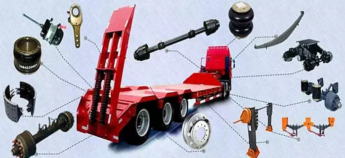
Full-floating axle
A full-floating axle is different from a semi-floating axle in several ways. A semi-floating axle is used for rear wheel drive cars, where it has a bearing mounted in the axle shaft. This axle supports the vehicle’s weight and transmits the drive torque from the transmission to the wheels. However, a semi-floating axle’s load capacity is limited by the size of the axle bearing. A full-floating axle, on the other hand, has the bearing mounted on the outside of the axle tube. The bearing is the only part of the axle that supports the vehicle, and the hub and bearing assembly are held together by a large nut.
The drive axle on a full-floating axle is splined at both ends so that it can easily be removed from the rear of a vehicle without removing the wheel. This type of axle makes it possible to change gears quickly and easily. Because of this, it’s not necessary to remove the wheels and tires in order to replace the axle. Instead, a common tool used to remove the axle from the wheel hub is an axle wrench.
Full-floating axles are more common in heavy-duty vehicles. The ability to carry heavy loads without causing the axle to break is a big advantage to full-floating axles. These axles require less maintenance and require less bends than traditional axles and may even be worth the extra investment if you have a heavy load to carry.
A full-floating axle allows the driver to change a broken axle shaft without having to remove the entire wheel. A full-floating axle will also allow the driver to remove the axle shaft without having to take off the wheel. Full-floating axles are also more durable than semi-floaters, which have weight resting on the axle tubes and housing.
While a full-floating axle is more expensive to manufacture, it is better for heavier vehicles that carry heavy loads. It is better to choose a full-floating axle if you have a heavy load or plan on towing.
Three-quarter floater
A three-quarter floating axle is a type of floating axle that’s a compromise between the full and semi-floating types. Its bearings are located on the axle casing rather than on the hub, which means that it’s less susceptible to axle breakdown. However, it’s not as robust as a full floating axle.
This design combines the benefits of fully-floating axles with the simplicity of a semi-floating axle. Instead of having multiple wheel bearings, a single wheel bearing is installed in the center of the hub. The hub is then keyed rigidly to the axle shaft, providing a connecting connection and maintaining wheel alignment.
While a full-floating axle is the most common style of truck axle, you may see the three-quarter floater on the side of a pickup. It was common for 3/4-ton Gms to use these axles until the 1980s. Dodge and Ford also used a semi-float axle called a Dana 60. The difference between the two types of axles is the amount of support provided by the axleshaft and hub, and the number of lug nuts on the axleshaft and hub are different.
The three-quarter floater axle drive assembly of the present invention is illustrated in FIG. 1. The axle housing comprises an elongated axle tube 12, a hub member 30, and a hub shaft 16. A hub member 30 is rotatably supported on the axle tube 12 by an anti-friction bearing assembly 42. The axle shaft is retained in place by a domed plate 26.
This axle design has two main advantages. First, it transfers the weight of the vehicle to the axle casing. It also helps transfer the driving torque and side thrust to the wheel. This type of axle also has a differential cross shaft, which limits inward axial movement of the axle shaft.
Dead axle
A Dead axle is a structural component that supports the rear wheel of a vehicle. It can either be straight or angled and is located behind the drive axle. Depending on the vehicle, the dead axle may be steerable. Tag axles are also common on agricultural equipment and certain heavy construction machinery. They are also known as lazy axles because they only contact the ground when a vehicle is carrying a significant load, thus saving tire wear. Dead axles may be rigid or flexible.
Some rear dead axles can also be configured as an air tank. The air is taken in and out of the rear dead axle through the port portions of the rear axle. This can reduce the size of the air tank. For this reason, it is a preferred design for rear dead axles. While most vehicles are equipped with two axles, the rear axle can be used to accommodate cargo.
FIG. 1 is a schematic plan view of a vehicle with two rear axles. The front axle is called the drive axle and the rear dead axle is called the dead axle. These components are located on a truck body frame. There are also battery and fuel tanks. They are used to distribute driving force from the front to rear wheels.
An axle is a crucial component of a vehicle. It transfers power from the engine to the wheels. A live axle is connected to the drive shaft and transmission, while a dead axle receives no direct power. This is the main difference between a live and dead axle. Although a dead axle is not as useful as a live one, it is still essential to understand what drives a car.
Dead axles are used in many vehicles for different purposes. Many large trucks are fitted with several of them for load bearing purposes. They also help distribute weight.
editor by czh 2022-11-30
China Professional Good Quality Hydraulic Decoiling and Feeding Machine with or Without Coil Car near me supplier
Product Description
Good quality Hydraulic decoiling and feeding machine with or without coil car
Decoiler –Automatic Hydraulic Decoiling And Feeding Machine:
The decoiler can handle the coil and be capable of feeding the roll into the
Slitting line, and also rewinding partially consumed rolls, so they can be restrapped whilst still on the mandrel, before returning to Coil Storage Facility
3 If you want to learn more about the product please login our website or contract to us
| hydraulic Pump Station : | 3KW | |
| Bearing weight: | 10T | |
| feeding roller’s width: | 1350mm | |
| Out line dimension of machine: | 2*5*2.5m | |
| Total weight: | 4.8T | |
For use at a later date.
Line composition:
Entry coil car – Uncoiler – Loop bridge – Side guider – Slitter head – Scrap winder – Loop bridge – Tension station – Recoiler – Exit coil car
Hydraulic system
Electrical system
Technical parameters:
Material: Cold rolled, hot rolled carbon steel, stainless steel, galvanized steel, silicon steel coil, p/o coil, aluminium coil
Width: Up to 2000mm
Thickness: 0.2-2.0mm, 0.3-3.0mm, 1.0-6.0mm, 2.0-12.0mm
Max. Coil weight: 35 tons max
Coil I. D.: 508mm/610mm/760mm
Coil O. D.: 2000mm max
Arbor diameter: 150mm/180mm/220mm
Drive: 380V/50Hz/3PH
Decoiling mode: Over/Under
Direction: According to requirement
Line speed: Up to 120 m/min
Max. Number of slits: 2-30 cuts
Narrowest strip width slit into: 10-25mm
Width cutting accuracy: ± 0.05mm(strip thickness≤ 1), ± 0.1mm(strip thickness>1.5mm)
Slitting burr: 5% of the thickness of material
Installation and training:
A. If buyers visit our factory and check the machine, we will teach you how to install and use the machine, and also train your workers/technician face to face.
B. Without visiting, we will send you user manual and video to teach you to install and operate.
C. If buyer needs our technician to go to your local factory, please arrange board and lodging and other necessary things
Our Services:
1. Customers` Design, Size, Color&Logo are accepted.
2. With15years professional manufacture experience
3. Prompt Delivery&Competitive Price
4. Main markets: Middle East, Europe, North America, Africa, Southeast Asia.
After-sales service:
1. We provide the technical support for whole life of our machines.
2. If buyers need the technician to go abroad, we will arrange the technician,
But the buyers should take all the cost, including visa, roundtripticket etc.
REMARKS:
1 The machine can according to your requirement to set the color
2 Within in 1 year if any parts go broken we will send new ones to replace for free
How to Calculate the Diameter of a Worm Gear

In this article, we will discuss the characteristics of the Duplex, Single-throated, and Undercut worm gears and the analysis of worm shaft deflection. Besides that, we will explore how the diameter of a worm gear is calculated. If you have any doubt about the function of a worm gear, you can refer to the table below. Also, keep in mind that a worm gear has several important parameters which determine its working.
Duplex worm gear
A duplex worm gear set is distinguished by its ability to maintain precise angles and high gear ratios. The backlash of the gearing can be readjusted several times. The axial position of the worm shaft can be determined by adjusting screws on the housing cover. This feature allows for low backlash engagement of the worm tooth pitch with the worm gear. This feature is especially beneficial when backlash is a critical factor when selecting gears.
The standard worm gear shaft requires less lubrication than its dual counterpart. Worm gears are difficult to lubricate because they are sliding rather than rotating. They also have fewer moving parts and fewer points of failure. The disadvantage of a worm gear is that you cannot reverse the direction of power due to friction between the worm and the wheel. Because of this, they are best used in machines that operate at low speeds.
Worm wheels have teeth that form a helix. This helix produces axial thrust forces, depending on the hand of the helix and the direction of rotation. To handle these forces, the worms should be mounted securely using dowel pins, step shafts, and dowel pins. To prevent the worm from shifting, the worm wheel axis must be aligned with the center of the worm wheel’s face width.
The backlash of the CZPT duplex worm gear is adjustable. By shifting the worm axially, the section of the worm with the desired tooth thickness is in contact with the wheel. As a result, the backlash is adjustable. Worm gears are an excellent choice for rotary tables, high-precision reversing applications, and ultra-low-backlash gearboxes. Axial shift backlash is a major advantage of duplex worm gears, and this feature translates into a simple and fast assembly process.
When choosing a gear set, the size and lubrication process will be crucial. If you’re not careful, you might end up with a damaged gear or 1 with improper backlash. Luckily, there are some simple ways to maintain the proper tooth contact and backlash of your worm gears, ensuring long-term reliability and performance. As with any gear set, proper lubrication will ensure your worm gears last for years to come.
Single-throated worm gear
Worm gears mesh by sliding and rolling motions, but sliding contact dominates at high reduction ratios. Worm gears’ efficiency is limited by the friction and heat generated during sliding, so lubrication is necessary to maintain optimal efficiency. The worm and gear are usually made of dissimilar metals, such as phosphor-bronze or hardened steel. MC nylon, a synthetic engineering plastic, is often used for the shaft.
Worm gears are highly efficient in transmission of power and are adaptable to various types of machinery and devices. Their low output speed and high torque make them a popular choice for power transmission. A single-throated worm gear is easy to assemble and lock. A double-throated worm gear requires 2 shafts, 1 for each worm gear. Both styles are efficient in high-torque applications.
Worm gears are widely used in power transmission applications because of their low speed and compact design. A numerical model was developed to calculate the quasi-static load sharing between gears and mating surfaces. The influence coefficient method allows fast computing of the deformation of the gear surface and local contact of the mating surfaces. The resultant analysis shows that a single-throated worm gear can reduce the amount of energy required to drive an electric motor.
In addition to the wear caused by friction, a worm wheel can experience additional wear. Because the worm wheel is softer than the worm, most of the wear occurs on the wheel. In fact, the number of teeth on a worm wheel should not match its thread count. A single-throated worm gear shaft can increase the efficiency of a machine by as much as 35%. In addition, it can lower the cost of running.
A worm gear is used when the diametrical pitch of the worm wheel and worm gear are the same. If the diametrical pitch of both gears is the same, the 2 worms will mesh properly. In addition, the worm wheel and worm will be attached to each other with a set screw. This screw is inserted into the hub and then secured with a locknut.
Undercut worm gear
Undercut worm gears have a cylindrical shaft, and their teeth are shaped in an evolution-like pattern. Worms are made of a hardened cemented metal, 16MnCr5. The number of gear teeth is determined by the pressure angle at the zero gearing correction. The teeth are convex in normal and centre-line sections. The diameter of the worm is determined by the worm’s tangential profile, d1. Undercut worm gears are used when the number of teeth in the cylinder is large, and when the shaft is rigid enough to resist excessive load.
The center-line distance of the worm gears is the distance from the worm centre to the outer diameter. This distance affects the worm’s deflection and its safety. Enter a specific value for the bearing distance. Then, the software proposes a range of suitable solutions based on the number of teeth and the module. The table of solutions contains various options, and the selected variant is transferred to the main calculation.
A pressure-angle-angle-compensated worm can be manufactured using single-pointed lathe tools or end mills. The worm’s diameter and depth are influenced by the cutter used. In addition, the diameter of the grinding wheel determines the profile of the worm. If the worm is cut too deep, it will result in undercutting. Despite the undercutting risk, the design of worm gearing is flexible and allows considerable freedom.
The reduction ratio of a worm gear is massive. With only a little effort, the worm gear can significantly reduce speed and torque. In contrast, conventional gear sets need to make multiple reductions to get the same reduction level. Worm gears also have several disadvantages. Worm gears can’t reverse the direction of power because the friction between the worm and the wheel makes this impossible. The worm gear can’t reverse the direction of power, but the worm moves from 1 direction to another.
The process of undercutting is closely related to the profile of the worm. The worm’s profile will vary depending on the worm diameter, lead angle, and grinding wheel diameter. The worm’s profile will change if the generating process has removed material from the tooth base. A small undercut reduces tooth strength and reduces contact. For smaller gears, a minimum of 14-1/2degPA gears should be used.
Analysis of worm shaft deflection
To analyze the worm shaft deflection, we first derived its maximum deflection value. The deflection is calculated using the Euler-Bernoulli method and Timoshenko shear deformation. Then, we calculated the moment of inertia and the area of the transverse section using CAD software. In our analysis, we used the results of the test to compare the resulting parameters with the theoretical ones.
We can use the resulting centre-line distance and worm gear tooth profiles to calculate the required worm deflection. Using these values, we can use the worm gear deflection analysis to ensure the correct bearing size and worm gear teeth. Once we have these values, we can transfer them to the main calculation. Then, we can calculate the worm deflection and its safety. Then, we enter the values into the appropriate tables, and the resulting solutions are automatically transferred into the main calculation. However, we have to keep in mind that the deflection value will not be considered safe if it is larger than the worm gear’s outer diameter.
We use a four-stage process for investigating worm shaft deflection. We first apply the finite element method to compute the deflection and compare the simulation results with the experimentally tested worm shafts. Finally, we perform parameter studies with 15 worm gear toothings without considering the shaft geometry. This step is the first of 4 stages of the investigation. Once we have calculated the deflection, we can use the simulation results to determine the parameters needed to optimize the design.
Using a calculation system to calculate worm shaft deflection, we can determine the efficiency of worm gears. There are several parameters to optimize gearing efficiency, including material and geometry, and lubricant. In addition, we can reduce the bearing losses, which are caused by bearing failures. We can also identify the supporting method for the worm shafts in the options menu. The theoretical section provides further information.
China OEM Fully Automatic Steel Coil 5t Hydraulic Decoiler with Loading Car near me manufacturer
Product Description
Fully Automatic Steel Coil 5T Hydraulic Decoiler With Loading Car
Decoiler –Automatic Hydraulic Decoiling And Feeding Machine:
The decoiler can handle the coil and be capable of feeding the roll into the
Slitting line, and also rewinding partially consumed rolls, so they can be restrapped whilst still on the mandrel, before returning to Coil Storage Facility
For use at a later date.
Line composition:
Entry coil car – Uncoiler – Loop bridge – Side guider – Slitter head – Scrap winder – Loop bridge – Tension station – Recoiler – Exit coil car
Hydraulic system
Electrical system
Technical parameters:
Material: Cold rolled, hot rolled carbon steel, stainless steel, galvanized steel, silicon steel coil, p/o coil, aluminium coil
Width: Up to 2000mm
Thickness: 0.2-2.0mm, 0.3-3.0mm, 1.0-6.0mm, 2.0-12.0mm
Max. Coil weight: 35 tons max
Coil I. D.: 508mm/610mm/760mm
Coil O. D.: 2000mm max
Arbor diameter: 150mm/180mm/220mm
Drive: 380V/50Hz/3PH
Decoiling mode: Over/Under
Direction: According to requirement
Line speed: Up to 120 m/min
Max. Number of slits: 2-30 cuts
Narrowest strip width slit into: 10-25mm
Width cutting accuracy: ± 0.05mm(strip thickness≤ 1), ± 0.1mm(strip thickness>1.5mm)
Slitting burr: 5% of the thickness of material
Installation and training:
A. If buyers visit our factory and check the machine, we will teach you how to install and use the machine, and also train your workers/technician face to face.
B. Without visiting, we will send you user manual and video to teach you to install and operate.
C. If buyer needs our technician to go to your local factory, please arrange board and lodging and other necessary things
Our Services:
1. Customers` Design, Size, Color&Logo are accepted.
2. With15years professional manufacture experience
3. Prompt Delivery&Competitive Price
4. Main markets: Middle East, Europe, North America, Africa, Southeast Asia.
After-sales service:
1. We provide the technical support for whole life of our machines.
2. If buyers need the technician to go abroad, we will arrange the technician,
But the buyers should take all the cost, including visa, roundtripticket etc.
REMARKS:
1 The machine can according to your requirement to set the color
2 Within in 1 year if any parts go broken we will send new ones to replace for free
3 If you want to learn more about the product please login our website or contract to us
| hydraulic Pump Station : | 3KW | |
| Bearing weight: | 10T | |
| feeding roller’s width: | 1350mm | |
| Out line dimension of machine: | 2*5*2.5m | |
| Total weight: | 4.8T | |
The Different Types of Splines in a Splined Shaft
A splined shaft is a machine component with internal and external splines. The splines are formed in 4 different ways: Involute, Parallel, Serrated, and Ball. You can learn more about each type of spline in this article. When choosing a splined shaft, be sure to choose the right 1 for your application. Read on to learn about the different types of splines and how they affect the shaft’s performance.
Involute splines
Involute splines in a splined shaft are used to secure and extend mechanical assemblies. They are smooth, inwardly curving grooves that resist separation during operation. A shaft with involute splines is often longer than the shaft itself. This feature allows for more axial movement. This is beneficial for many applications, especially in a gearbox.
The involute spline is a shaped spline, similar to a parallel spline. It is angled and consists of teeth that create a spiral pattern that enables linear and rotatory motion. It is distinguished from other splines by the serrations on its flanks. It also has a flat top. It is a good option for couplers and other applications where angular movement is necessary.
Involute splines are also called involute teeth because of their shape. They are flat on the top and curved on the sides. These teeth can be either internal or external. As a result, involute splines provide greater surface contact, which helps reduce stress and fatigue. Regardless of the shape, involute splines are generally easy to machine and fit.
Involute splines are a type of splines that are used in splined shafts. These splines have different names, depending on their diameters. An example set of designations is for a 32-tooth male spline, a 2,500-tooth module, and a 30 degree pressure angle. An example of a female spline, a fillet root spline, is used to describe the diameter of the splined shaft.
The effective tooth thickness of splines is dependent on the number of keyways and the type of spline. Involute splines in splined shafts should be designed to engage 25 to 50 percent of the spline teeth during the coupling. Involute splines should be able to withstand the load without cracking.
Parallel splines
Parallel splines are formed on a splined shaft by putting 1 or more teeth into another. The male spline is positioned at the center of the female spline. The teeth of the male spline are also parallel to the shaft axis, but a common misalignment causes the splines to roll and tilt. This is common in many industrial applications, and there are a number of ways to improve the performance of splines.
Typically, parallel splines are used to reduce friction in a rotating part. The splines on a splined shaft are narrower on the end face than the interior, which makes them more prone to wear. This type of spline is used in a variety of industries, such as machinery, and it also allows for greater efficiency when transmitting torque.
Involute splines on a splined shaft are the most common. They have equally spaced teeth, and are therefore less likely to crack due to fatigue. They also tend to be easy to cut and fit. However, they are not the best type of spline. It is important to understand the difference between parallel and involute splines before deciding on which spline to use.
The difference between splined and involute splines is the size of the grooves. Involute splines are generally larger than parallel splines. These types of splines provide more torque to the gear teeth and reduce stress during operation. They are also more durable and have a longer life span. And because they are used on farm machinery, they are essential in this type of application.
Serrated splines
A Serrated Splined Shaft has several advantages. This type of shaft is highly adjustable. Its large number of teeth allows large torques, and its shorter tooth width allows for greater adjustment. These features make this type of shaft an ideal choice for applications where accuracy is critical. Listed below are some of the benefits of this type of shaft. These benefits are just a few of the advantages. Learn more about this type of shaft.
The process of hobbing is inexpensive and highly accurate. It is useful for external spline shafts, but is not suitable for internal splines. This type of process forms synchronized shapes on the shaft, reducing the manufacturing cycle and stabilizing the relative phase between spline and thread. It uses a grinding wheel to shape the shaft. CZPT Manufacturing has a large inventory of Serrated Splined Shafts.
The teeth of a Serrated Splined Shaft are designed to engage with the hub over the entire circumference of the shaft. The teeth of the shaft are spaced uniformly around the spline, creating a multiple-tooth point of contact over the entire length of the shaft. The results of these analyses are usually satisfactory. But there are some limitations. To begin with, the splines of the Serrated Splined Shaft should be chosen carefully. If the application requires large-scale analysis, it may be necessary to modify the design.
The splines of the Serrated Splined Shaft are also used for other purposes. They can be used to transmit torque to another device. They also act as an anti-rotational device and function as a linear guide. Both the design and the type of splines determine the function of the Splined Shaft. In the automobile industry, they are used in vehicles, aerospace, earth-moving machinery, and many other industries.
Ball splines
The invention relates to a ball-spinned shaft. The shaft comprises a plurality of balls that are arranged in a series and are operatively coupled to a load path section. The balls are capable of rolling endlessly along the path. This invention also relates to a ball bearing. Here, a ball bearing is 1 of the many types of gears. The following discussion describes the features of a ball bearing.
A ball-splined shaft assembly comprises a shaft with at least 1 ball-spline groove and a plurality of circumferential step grooves. The shaft is held in a first holding means that extends longitudinally and is rotatably held by a second holding means. Both the shaft and the first holding means are driven relative to 1 another by a first driving means. It is possible to manufacture a ball-splined shaft in a variety of ways.
A ball-splined shaft features a nut with recirculating balls. The ball-splined nut rides in these grooves to provide linear motion while preventing rotation. A splined shaft with a nut that has recirculating balls can also provide rotary motion. A ball splined shaft also has higher load capacities than a ball bushing. For these reasons, ball splines are an excellent choice for many applications.
In this invention, a pair of ball-spinned shafts are housed in a box under a carrier device 40. Each of the 2 shafts extends along a longitudinal line of arm 50. One end of each shaft is supported rotatably by a slide block 56. The slide block also has a support arm 58 that supports the center arm 50 in a cantilever fashion.
Sector no-go gage
A no-go gauge is a tool that checks the splined shaft for oversize. It is an effective way to determine the oversize condition of a splined shaft without removing the shaft. It measures external splines and serrations. The no-go gage is available in sizes ranging from 19mm to 130mm with a 25mm profile length.
The sector no-go gage has 2 groups of diametrally opposed teeth. The space between them is manufactured to a maximum space width and the tooth thickness must be within a predetermined tolerance. This gage would be out of tolerance if the splines were measured with a pin. The dimensions of this splined shaft can be found in the respective ANSI or DIN standards.
The go-no-go gage is useful for final inspection of thread pitch diameter. It is also useful for splined shafts and threaded nuts. The thread of a screw must match the contour of the go-no-go gage head to avoid a no-go condition. There is no substitute for a quality machine. It is an essential tool for any splined shaft and fastener manufacturer.
The NO-GO gage can detect changes in tooth thickness. It can be calibrated under ISO17025 standards and has many advantages over a non-go gage. It also gives a visual reference of the thickness of a splined shaft. When the teeth match, the shaft is considered ready for installation. It is a critical process. In some cases, it is impossible to determine the precise length of the shaft spline.
The 45-degree pressure angle is most commonly used for axles and torque-delivering members. This pressure angle is the most economical in terms of tool life, but the splines will not roll neatly like a 30 degree angle. The 45-degree spline is more likely to fall off larger than the other two. Oftentimes, it will also have a crowned look. The 37.5 degree pressure angle is a compromise between the other 2 pressure angles. It is often used when the splined shaft material is harder than usual.