Product Description
New/used Heavy duty Hydraulic Lifting 10/8units car trailer car carrier semi trailer 2/3 axles for van cargo small cars transport Kazakhstan Central Asia
Our main products include full series products of CNHTC(HOWO,STR,Golden Prince,etc.), buses, trailers,
including dump truck, tractor truck, concrete mier truck, sprinkler truck, water/Oil tank truck, truck mounted crane,
concrete pump truck.etc, low bed semi-trailer, flatbed semi-trailer, bulk cement semi-trailer,
skeleton semi-trailer and spare parts for them.
Car carrier trailer Specifications(The configuration can be customized)
|
Hydraulic Loading Cars CarrierTransportation Trailer |
|||||
|
Size |
Axle No |
Rating Capacity |
Tire Qty |
Tire Model |
|
|
6 Cars Loading |
2 Axles |
50Tons |
8 sets |
8.25R20 |
|
|
10 Cars Loading |
3 Axles |
60-70Tons |
12 sets |
10.00R20 |
|
|
More than 10 cars |
4 Axles |
80Tons |
16 sets |
11.00R20 |
|
|
Rear tread(mm) |
1840/1840 |
||||
|
Outside Dimension L×W×H |
15800-21000x2400x3000 mm |
||||
|
Main Frame |
Q345B manganese plates, automatic submerged arc welded |
||||
|
Floor |
Steel Sheet 3mm thickness or CZPT plate |
||||
|
Suspension |
Steel leaf spring suspension system |
||||
|
Rated load |
30-50 T |
||||
|
Pin Size |
2′ and 3.5′ inter-changeable Pin |
||||
|
Spare Wheel Carrier |
One set of spare wheel carrier including a riser. |
||||
|
Braking System |
2-Line compressed air brake system on all wheels with additional parking brake. |
||||
|
Brake Air Chamber |
Automatic Air Chambers |
||||
|
Electrical System |
1. Voltage: 24v 2. Receptacle: 7 ways(7 wire harness) |
||||
|
Accessory |
One tooling box with a set of standard trailer tool |
||||
|
Landing gear |
Capacity of 28ton,factory brand |
||||
|
Lights System |
LED electrical system to international standards includes taillights, sidelights and direction indicators. |
||||
Company information
HOWO SPECIAL TRUCK LTD is 1 of the main exporters of Chinese truck parts which is authorized by Ministry of Commerce
Our main products include full series products of CNHTC(HOWO,STR,Golden Prince,etc.), and spare parts for them. At the same time, we are always glad to provide professional suggestion for your orders,related technical support, and perfect after-sales services.
Staff of our company can provide the trucks meeting the requirement of customers at the best price. We have many years of experience in exporting trucks. We have not only the certificate and license of truck export and also strict quality management,fast and convenient channel of goods delivery, strict examination in quality and quantity of products, professional packing, professional and reliable loading goods,ontime delivery and competitive prices.if you want to buy tractor truck,please contact us.
We sincerely hope to cooperate with you to expand market in your country!
Our main Overseas Business Scope
-All types of brand new and used heavy duty truck and light duty trucks
– Special modified vehicle
– All types of semitrailer
– Construction equipment&Machinery
– Pickup, VAN, Bus
– Spare parts- Service & Maintenance
Our Advantages
(1)Competitive Factory Price and Excellent Quality
(2)More than 20 years’ experience as a manufacturer
(3)Products Quality Certification SGS CCC ISO
(4)Perfect after-sale service
(5)Customized products available with us
(6)Export to more than 50 countries and regions
FAQ
| Q1: Minimum order quantity? |
| A: MOQ is 1 unit. |
| Q2: Production period? |
| A: Within 7 days since the moment we got your down payment Besides in large quantities or imported |
| Q3: Payment term? |
| A:TT: 100% T/T should be paid before delivery Besides in large quantities: 50% T/T as deposit, the balance should be paid before delivery, Or LC,Western union |
| Q4: Shipping? |
| A: by international courier service, such as DHL, TNT, UPS, or Fedex. The goods above $1000 or a container can be shipped by sea |
HOWO SPECIAL TRUCK Ltd is 1 of the main exporters of Chinese trucks which is authorized by Ministry of commerceStaff of our company can provide the trucks meeting the requirement of customers at the best price.
We have 20 years of experience in exporting trucks.
We sincerely hope to cooperate with you to expand market in your country!
/* January 22, 2571 19:08:37 */!function(){function s(e,r){var a,o={};try{e&&e.split(“,”).forEach(function(e,t){e&&(a=e.match(/(.*?):(.*)$/))&&1
| After-sales Service: | Has |
|---|---|
| Warranty: | Has |
| Type: | Semi-Trailer |
| Load Capacity: | 80T |
| Certification: | ECE, GCC, CE, ISO9001, DOT, CCC, ISO/TS16949 |
| Wheel Base: | 7000-8000mm |
| Samples: |
US$ 18500/Piece
1 Piece(Min.Order) | |
|---|
| Customization: |
Available
| Customized Request |
|---|

Where can I find information on axle load limits for various types of vehicles?
When seeking information on axle load limits for different types of vehicles, there are several reliable sources where you can find the necessary information. Here’s a detailed explanation of where you can find information on axle load limits:
1. Vehicle Owner’s Manual:
The first and most accessible source of information on axle load limits is the vehicle owner’s manual. The owner’s manual provided by the vehicle manufacturer typically includes important details about the vehicle’s specifications, including axle load limits. Look for sections related to vehicle loading, weight distribution, or axle specifications to find the recommended load limits for each axle of your specific vehicle model.
2. Government Transportation Authorities:
Government transportation authorities, such as departments of transportation or road transport authorities, often provide guidelines and regulations regarding vehicle weight limits, including axle load limits. These authorities establish and enforce weight restrictions to ensure road safety and prevent damage to infrastructure. Visit the website of your local or national transportation authority to access relevant regulations or guidelines pertaining to axle load limits for various types of vehicles.
3. Commercial Vehicle Regulations:
If you are specifically interested in axle load limits for commercial vehicles, such as trucks or buses, consult the commercial vehicle regulations applicable in your region. These regulations are established to ensure safe and efficient operation of commercial vehicles on public roads. Regulatory bodies responsible for commercial vehicle operations often provide detailed information on axle load limits, weight distribution requirements, and other related specifications.
4. Vehicle Manufacturer or Dealer:
If you require axle load limit information for a specific vehicle model or variant, contacting the vehicle manufacturer or a local authorized dealer can be helpful. They can provide accurate and up-to-date information specific to your vehicle. Provide them with the vehicle identification number (VIN) or other relevant details to ensure they can assist you accurately.
5. Online Resources and Databases:
There are online resources and databases dedicated to providing information on vehicle specifications, including axle load limits. These resources may include vehicle data websites, forums, or government databases that compile and provide access to vehicle specifications and regulatory information. Conduct an internet search using relevant keywords to find reliable online sources that offer information on axle load limits for various types of vehicles.
When seeking information on axle load limits, it’s crucial to ensure that the information you obtain is accurate, up-to-date, and applicable to your specific vehicle and jurisdiction. Regulations and load limits can vary depending on the country, region, vehicle type, and other factors. Therefore, it is advisable to consult official sources or seek professional advice to ensure compliance with applicable regulations and ensure safe and legal operation of your vehicle.

Can you provide insights into the advancements in axle technology in recent years?
In recent years, there have been significant advancements in axle technology to enhance performance, efficiency, and safety in vehicles. Here are some insights into the key advancements:
- Lightweight Materials:
- Electronic Differential:
- Advanced Axle Bearings:
- Electric Axles:
- Active Suspension Integration:
- Improved Sealing and Lubrication:
- Autonomous Vehicle Integration:
One notable advancement is the use of lightweight materials in axle construction. Manufacturers have increasingly utilized materials such as aluminum alloys and high-strength steels to reduce the weight of axles without compromising strength and durability. Lighter axles contribute to improved fuel efficiency and overall vehicle performance.
Electronic differentials, also known as eDiffs, have gained popularity in recent years. They utilize sensors, actuators, and control algorithms to monitor and distribute torque between the wheels more efficiently. Electronic differentials enhance traction, stability, and handling by actively managing torque distribution, especially in vehicles equipped with advanced stability control systems.
Axle bearings have seen advancements in design and materials to reduce friction, improve efficiency, and enhance durability. For example, the use of roller bearings or tapered roller bearings has become more prevalent, offering reduced frictional losses and improved load-carrying capacity. Some manufacturers have also introduced sealed or maintenance-free bearings to minimize maintenance requirements.
With the rise of electric vehicles (EVs) and hybrid vehicles, electric axles have emerged as a significant technological advancement. Electric axles integrate electric motors, power electronics, and gear systems into the axle assembly. They eliminate the need for traditional drivetrain components, simplify vehicle packaging, and offer benefits such as instant torque, regenerative braking, and improved energy efficiency.
Advancements in axle technology have facilitated the integration of active suspension systems into axle designs. Active suspension systems use sensors, actuators, and control algorithms to adjust the suspension characteristics in real-time, providing improved ride comfort, handling, and stability. Axles with integrated active suspension components offer more precise control over vehicle dynamics.
Axles have seen advancements in sealing and lubrication technologies to enhance durability and minimize maintenance requirements. Improved sealing systems help prevent contamination and retain lubricants, reducing the risk of premature wear or damage. Enhanced lubrication systems with better heat dissipation and reduced frictional losses contribute to improved efficiency and longevity.
The development of autonomous vehicles has spurred advancements in axle technology. Axles are being designed to accommodate the integration of sensors, actuators, and communication systems necessary for autonomous driving. These advancements enable seamless integration with advanced driver-assistance systems (ADAS) and autonomous driving features, ensuring optimal performance and safety.
It’s important to note that the specific advancements in axle technology can vary across different vehicle manufacturers and models. Furthermore, ongoing research and development efforts continue to drive further innovations in axle design, materials, and functionalities.
For the most up-to-date and detailed information on axle technology advancements, it is advisable to consult automotive manufacturers, industry publications, and reputable sources specializing in automotive technology.

Can you explain the importance of axle alignment for vehicle stability and handling?
Axle alignment plays a crucial role in ensuring vehicle stability and handling characteristics. Proper alignment of the axles is essential for maintaining optimal tire contact with the road surface, minimizing tire wear, maximizing traction, and promoting safe and predictable handling. Here are the key reasons why axle alignment is important:
- Tire Wear and Longevity:
- Optimal Traction:
- Steering Response and Stability:
- Reduced Rolling Resistance:
- Vehicle Safety:
Correct axle alignment helps distribute the vehicle’s weight evenly across all four tires. When the axles are properly aligned, the tires wear evenly, reducing the risk of premature tire wear and extending their lifespan. Misaligned axles can cause uneven tire wear patterns, such as excessive wear on the inner or outer edges of the tires, leading to the need for premature tire replacement.
Proper axle alignment ensures that the tires maintain optimal contact with the road surface. When the axles are aligned correctly, the tires can evenly distribute the driving forces, maximizing traction and grip. This is particularly important during acceleration, braking, and cornering, as proper alignment helps prevent tire slippage and improves overall vehicle stability.
Axle alignment directly affects steering response and stability. When the axles are properly aligned, the vehicle responds predictably to driver inputs, providing precise and accurate steering control. Misaligned axles can lead to steering inconsistencies, such as pulling to one side or requiring constant correction, compromising vehicle stability and handling.
Proper axle alignment helps reduce rolling resistance, which is the force required to move the vehicle forward. When the axles are aligned correctly, the tires roll smoothly and effortlessly, minimizing energy loss due to friction. This can contribute to improved fuel efficiency and reduced operating costs.
Correct axle alignment is crucial for ensuring vehicle safety. Misaligned axles can affect the vehicle’s stability, especially during emergency maneuvers or sudden lane changes. Proper alignment helps maintain the intended handling characteristics of the vehicle, reducing the risk of loss of control and improving overall safety.
To achieve proper axle alignment, several key parameters are considered, including camber, toe, and caster angles. Camber refers to the vertical tilt of the wheel when viewed from the front, toe refers to the angle of the wheels in relation to each other when viewed from above, and caster refers to the angle of the steering axis in relation to vertical when viewed from the side. These alignment angles are adjusted to meet the vehicle manufacturer’s specifications and ensure optimal performance.
It’s important to note that factors such as road conditions, driving habits, and vehicle modifications can affect axle alignment over time. Regular maintenance and periodic alignment checks are recommended to ensure that the axles remain properly aligned, promoting vehicle stability, handling, and safety.


editor by CX 2024-04-04
China Professional China Factory Sale Heavy Duty 13 16 18 20 25 Ton Hydraulic Turnable Steering Trailer Axle (03) broken axle cost
Product Description
Company Profile
HangZhou Hilite Auto Parts Co., Ltd., Established In 2012, Professional Chinese Supplier Of Trailer Parts, Truck Parts And Agricultural Vehicle Parts. We Are a Professional & Modern Company Who Specializes In R&D, Production And Sales Of Leaf Spring ,Axles, Suspension,Brake System(Relay Valve,Abs…),Tank Trailer Accessories,Etc.
Our Advantages
Our Products Are Mainly Sold To Southeast Asia, Europe, Central And South America, The Middle East And Africa. Our Value Is To Gain More Market Share By Profit&Value Delivery Our Customers And Partners. CZPT Parts is Compatible with BP / Fw Accessories, Can Be Couple with SINOTRUCK/BENZ/FAW/XIHU (WEST LAKE) DIS.FENG… Trucks & Trailers. CZPT Is Committed To Providing Customer With Professional And Precise Services, High-Quality Products with Sufficient Experiecne.
OEM & Packing
Product Description
| Axle Type | Max Capacity(t) | Track(mm) | Brake (mm) |
Spring Seat Installation | Axle Beam (mm) |
Centre Distance Of Brake Chamber(mm) | Wheel Fixing | Total Length (mm) |
Recommend Wheel | Axle Wright (kg) |
||
| Stud (ISO) | P.C.D(mm) | H(mm) | ||||||||||
| HLT-3AC5-8 | 8 | 1850 | 420*150 | ≥1080 | 127 | 428 | 10*M22*1.5 | 335 | 280.8 | ~2145 | 7.5V-20 | 323 |
| HLT-3AC5-10 | 13 | 1840 | 420*180 | ≥970 | 127 | 380 | 10*M22*1.5 | 335 | 280.8 | ~2180 | 7.5V-20 | 342 |
| HLT-3AC5-10 | 13 | 1840 | 420*180 | ≥930 | 150 | 380 | 10*M22*1.5 | 335 | 280.8 | ~2180 | 7.5V-20 | 340 |
| HLT-3AC5-11 | 14 | 1840 | 420*220 | ≥930 | 150 | 340 | 10*M22*1.5 | 335 | 280.8 | ~2180 | 7.5V-20 | 358 |
| HLT-3AC5-11 | 15 | 1850 | 420*180 | ≥940 | 150 | 390 | 10*M22*1.5 | 335 | 280.8 | ~2200 | 8.0V-20 | 370 |
| HLT-3AC5-11 | 16 | 1850 | 420*220 | ≥940 | 150 | 350 | 10*M22*1.5 | 335 | 280.8 | ~2200 | 8.0V-20 | 388 |
| HLT-3AC5-12 | 20 | 1850 | 420*220 | ≥940 | 150 | 345 | 10*M24*1.5 | 335 | 280.8 | ~2247 | 8.0V-20 | 430 |
| HLT-3AC5-12 | 25 | 1850 | 420*220 | ≥940 | 150 | 340 | 10*M24*1.5 | 335 | 280.8 | ~2215 | 8.0V-20 | 474 |
CZPT Specializes In R&D, Production And Sales Of Auto Leaf Springs, American &German Axles, Leaf Spring Suspensions, Air Suspensions, Hydraulic Suspensions, Rigid Suspensions And Other Types Of Suspensions, Single/Double Landing Gear, Electric Landing Gear, Hydraulic Landing Gear And Various Types Of Landing Gear , As Well As Tank Trailer Accessories Such As Manhole Covers, Discharge Valves, Subsea Valves, Etc. 500,000+ Types, One Stop Shopping For All.
Quality Comparasion
. Superior One-Piece Low-Alloy Axle Tube, Strong Carrying Capacity & High Bending Strength.
. Hardening And Tempering As a Whole, Cnc Machining.
. Brake Linings, Environment-Friendly Andnon-Asbestos, Wear Life Increased 25%.
. Xhp Mobil Grease To Lengthenmaintenance-Free Time.
. Bearing Is Designed For Heavy-Dutyvehicles, Famous Domestic Brand.
. Interchangeable Brake Components Ands-Camshaft Make Brake Action More Flexible.
Certifications
CZPT Provide Guaranteed Services For All Products, Respect And Pay Attention To The Opinions Of Customers And Partners, Including Customizing And Developing New Products According To Customers’ Requirements, Believing Customer Satisfaction Is Our CZPT Pursuit. More Than 76% Of The Customers Who Have Used Hilite Products Have Become Our Loyal Customers, Who Have Established An Incredible Brand Effect For Us In The Local Area.
Factory View
We Would Like To Cooperate With You To Create More New Bonds In The Future.
FAQ
1Q: CAN YOU DESIGN AND PRODUCE THE PRODUCTS WE WANT?
A:We Have Rich Experience And Strong Technical Support To Design And Produce By Your Samples Or Drawings.Warmly Welcomed For Your Samples Or Drawing.
2Q:WHAT’S THE PROCESS OF PURCHASING ORDERS FROM YOU?
A:1.Send Us Your Specific Demand,Such As Oem Numbers, Photos, Trailer Models,Ect.
2.Confirm Our Quotation With Photos And Other Detials.
3.Negotiate About All Details You Need: Packing, Delivery Terms,Warranty, Ect.
4.Sign The Contract For The Payment,We Will Make The Production On Time.
3Q.WHAT IS YOUR TERMS OF PAYMENT?
A: T/T 30% As Deposit, And 70% Before Delivery.
L/C,T/T,D/P, Western Union,Paypal,Money Gram, Others
Photos And Videos Of The Products Will Be Provided Before Your Balance Payment.
4Q :WE WANT TO TRY IN A SMALL QUANTITY AS TRIAL ORDER,BUT LESS THAN YOUR MOQ. WHAT IS YOUR POLICY?
Sample Test And Sample Orders Could Be Accepted If We Have Ready Parts In Stock. /* January 22, 2571 19:08:37 */!function(){function s(e,r){var a,o={};try{e&&e.split(“,”).forEach(function(e,t){e&&(a=e.match(/(.*?):(.*)$/))&&1
| After-sales Service: | 12 Months |
|---|---|
| Condition: | New |
| Axle Number: | 1 |
| Application: | Trailer |
| Certification: | ISO, CCC BV SGS TUV |
| Material: | Steel |
| Samples: |
US$ 1/Piece
1 Piece(Min.Order) | |
|---|
| Customization: |
Available
| Customized Request |
|---|

What is the role of axles in electric vehicles, and how do they differ from traditional axles?
Electric vehicles (EVs) have unique requirements when it comes to their drivetrain systems, including the axles. The role of axles in EVs is similar to traditional vehicles, but there are some key differences. Here’s a detailed explanation of the role of axles in electric vehicles and how they differ from traditional axles:
Role of Axles in Electric Vehicles:
The primary role of axles in electric vehicles is to transmit torque from the electric motor(s) to the wheels, enabling vehicle propulsion. The axles connect the motor(s) to the wheels and provide support for the weight of the vehicle. Axles are responsible for transferring the rotational force generated by the electric motor(s) to the wheels, allowing the vehicle to move forward or backward.
In electric vehicles, the axles are an integral part of the drivetrain system, which typically includes an electric motor(s), power electronics, and a battery pack. The axles play a crucial role in ensuring efficient power transfer and delivering the desired performance and handling characteristics of the vehicle.
Differences from Traditional Axles:
While the fundamental role of axles in electric vehicles is the same as in traditional vehicles, there are some notable differences due to the unique characteristics of electric propulsion systems:
1. Integration with Electric Motors: In electric vehicles, the axles are often integrated with the electric motors. This means that the motor(s) and axle assembly are combined into a single unit, commonly referred to as an “electric axle” or “e-axle.” This integration helps reduce the overall size and weight of the drivetrain system and simplifies installation in the vehicle.
2. High Torque Requirements: Electric motors generate high amounts of torque from the moment they start, providing instant acceleration. As a result, axles in electric vehicles need to handle higher torque loads compared to traditional axles. They are designed to withstand the torque output of the electric motor(s) and efficiently transmit it to the wheels.
3. Regenerative Braking: Electric vehicles often utilize regenerative braking, which converts the vehicle’s kinetic energy into electrical energy and stores it in the battery. The axles in electric vehicles may incorporate systems or components that enable regenerative braking, such as sensors, controllers, and electric brake actuators.
4. Space Optimization: Electric vehicles often have different packaging requirements compared to traditional internal combustion engine vehicles. The axles in electric vehicles are designed to accommodate the space constraints and specific layout of the vehicle, considering the placement of the battery pack, electric motor(s), and other components.
5. Weight Considerations: Electric vehicles strive to optimize weight distribution to enhance efficiency and handling. Axles in electric vehicles may be designed with lightweight materials or innovative construction techniques to minimize weight while maintaining structural integrity and durability.
It’s important to note that the specific design and characteristics of axles in electric vehicles can vary depending on the vehicle manufacturer, drivetrain configuration (e.g., front-wheel drive, rear-wheel drive, all-wheel drive), and other factors. Automotive manufacturers and suppliers continually innovate and develop new axle technologies to meet the evolving demands of electric vehicle propulsion systems.

Are there specific maintenance tips to extend the lifespan of my vehicle’s axles?
Maintaining the axles of your vehicle is crucial for ensuring their longevity, performance, and overall safety. Here are some specific maintenance tips to extend the lifespan of your vehicle’s axles:
- Regular Inspection:
- Lubrication:
- Seal Inspection and Replacement:
- Proper Loading and Towing:
- Driving Techniques:
- Regular Wheel Alignment:
- Proper Tire Inflation:
- Service Intervals:
Perform regular visual inspections of the axles to check for any signs of damage, leaks, or excessive wear. Look for cracks, bends, or rust on the axle housing, and inspect the axle shafts, seals, and boots. Early detection of issues can help prevent further damage and costly repairs.
Follow the manufacturer’s recommendations for axle lubrication. Proper lubrication helps reduce friction and wear on the axle components. Regularly check the axle’s lubricant level and quality, and replace it as necessary. Use the recommended lubricant type and viscosity for your specific axle.
Check the axle seals for any signs of leaks, such as fluid accumulation around the axle ends. Leaking seals can allow contaminants to enter the axle assembly, leading to premature wear and damage. Replace worn or damaged seals promptly to maintain proper lubrication and prevent contamination.
Ensure that you do not exceed the weight capacity of your vehicle’s axles. Overloading or towing beyond the recommended limits can put excessive stress on the axles, leading to premature wear or failure. Be mindful of the payload and towing capacity specified by the vehicle manufacturer.
Adopt proper driving techniques to minimize stress on the axles. Avoid sudden acceleration, aggressive cornering, and harsh braking, as these actions can subject the axles to excessive forces. Additionally, be cautious when driving over rough terrain or obstacles to prevent impacts that could damage the axles.
Maintain proper wheel alignment to prevent excessive strain on the axles. Misaligned wheels can put uneven loads on the axles, leading to accelerated wear. Regularly check and adjust the wheel alignment as per the manufacturer’s recommendations.
Ensure that your vehicle’s tires are properly inflated according to the recommended tire pressure. Underinflated or overinflated tires can affect the load distribution on the axles and increase the risk of axle damage. Regularly check and maintain the correct tire pressure.
Follow the recommended service intervals for your vehicle, which may include axle inspections, lubricant changes, and other maintenance tasks. Adhering to these intervals ensures that the axles are properly maintained and any potential issues are addressed in a timely manner.
It’s important to consult your vehicle’s owner’s manual for specific maintenance guidelines and intervals provided by the manufacturer. Additionally, if you notice any unusual noises, vibrations, or handling issues related to the axles, it is advisable to have your vehicle inspected by a qualified mechanic to identify and address any potential axle problems promptly.
What are the factors to consider when choosing an axle for a custom-built vehicle?
Choosing the right axle for a custom-built vehicle is crucial for ensuring optimal performance, durability, and safety. Here are several key factors to consider when selecting an axle for a custom-built vehicle:
- Vehicle Type and Intended Use:
- Axle Type:
- Weight Capacity:
- Axle Ratio:
- Braking System Compatibility:
- Suspension Compatibility:
- Aftermarket Support:
- Budget:
Consider the type of vehicle you are building and its intended use. Factors such as vehicle weight, power output, terrain (on-road or off-road), towing capacity, and payload requirements will influence the axle selection. Off-road vehicles may require axles with higher strength and durability, while performance-oriented vehicles may benefit from axles that can handle increased power and torque.
Choose the appropriate axle type based on your vehicle’s drivetrain configuration. Common axle types include solid axles (live axles) and independent axles. Solid axles are often used in heavy-duty applications and off-road vehicles due to their robustness and ability to handle high loads. Independent axles offer improved ride quality and handling characteristics but may have lower load-carrying capacities.
Determine the required weight capacity of the axle based on the vehicle’s weight and intended payload. It’s crucial to select an axle that can handle the anticipated loads without exceeding its weight rating. Consider factors such as cargo, passengers, and accessories that may contribute to the overall weight.
Choose an axle ratio that matches your vehicle’s powertrain and desired performance characteristics. The axle ratio affects the torque multiplication between the engine and wheels, influencing acceleration, towing capability, and fuel efficiency. Higher axle ratios provide more torque multiplication for improved low-end power but may sacrifice top-end speed.
Ensure that the chosen axle is compatible with your vehicle’s braking system. Consider factors such as the axle’s mounting provisions for brake calipers, rotor size compatibility, and the need for an anti-lock braking system (ABS) if required.
Consider the compatibility of the chosen axle with your vehicle’s suspension system. Factors such as axle mounting points, suspension geometry, and overall ride height should be taken into account. Ensure that the axle can be properly integrated with your chosen suspension components and that it provides sufficient ground clearance for your specific application.
Consider the availability of aftermarket support for the chosen axle. This includes access to replacement parts, upgrade options, and technical expertise. A robust aftermarket support network can be beneficial for future maintenance, repairs, and customization needs.
Set a realistic budget for the axle selection, keeping in mind that high-performance or specialized axles may come at a higher cost. Balance your requirements with your budget to find the best axle option that meets your needs without exceeding your financial limitations.
When choosing an axle for a custom-built vehicle, it’s recommended to consult with knowledgeable professionals, experienced builders, or reputable axle manufacturers. They can provide valuable guidance, assist in understanding technical specifications, and help you select the most suitable axle for your specific custom vehicle project.
editor by CX 2024-03-29
China factory 13t 16tons American Type Hydraulic Tractor Torsion Semi Trailer Axle cv axle replacement cost
Product Description
Product Description
Our trailer axles are suitable for American and German trucks. We have many models. We can produce American & German Axles of various specifications according to your drawings, sample or specific parameters you give us.
|
Product Name |
Trailer Axle |
|
Type |
American drum type |
|
Capacity |
13T, 15T, 16T, 20T |
|
Total Length |
About 2185 mm (According to the model) |
|
Weight |
About 330 KG (According to the model) |
|
Material |
Iron |
|
Color |
Black |
|
Brand |
CCQ |
|
Package |
Carton, wooden box |
|
Quality |
Super |
|
Port |
China Port |
|
Payment |
T/T, L/C, D/P, D/A, MoneyGram, Credit Card, PayPal, Western Union |
|
Service |
OEM, ODM |
Accessories
It adopts high-quality accessories from major brands at home and abroad, and global standard American
axle specifications. It has strong practicability, low price and convenient maintenance.
Axle
The factory produces its own shaft tube with quality assurance and cost advantage. The assembly process
strictly abides by international quality standards to create high-quality products.
| Inboard drum series trailer axle | ||||||||||||
| Axle Type | Max Capacity (T) |
Track L2 (mm) |
Brake (mm) |
Spring Seat Installation | Axle Beam (mm) |
Centre Distance Of Brake Chamber (mm) |
Wheel Fixing | Total Length (mm) |
Recommended Wheel | Axle Weight (kg) |
||
| Stud | P.C.D (mm) |
H (mm) |
||||||||||
| HRD-UI08 | 8 | 1850 | 420*150 | ≥1080 | Round 127 | 428 | 10*M22*1.5 ISO | 335 | 280.8 | ~2145 | 7.5V-20 | 323 |
| HRD-U13I1 | 13 | 1840 | 420*180 | ≥970 | Round 127 | 388 | 10*M22*1.5 ISO | 285.75 | 220.8 | ~2180 | 7.5V-20 | 360 |
| HRD-U13I2 | 13 | 1840 | 420*180 | ≥970 | Round 127 | 382 | 10*M22*1.5 ISO | 335 | 280.8 | ~2180 | 7.5V-20 | 342 |
| HRD-U13I3 | 13 | 1840 | 420*180 | ≥930 | Square 150 | 388 | 10*M22*1.5 ISO | 285.75 | 220.8 | ~2180 | 7.5V-20 | 358 |
| HRD-U13I4 | 13 | 1840 | 420*180 | ≥930 | Square 150 | 382 | 10*M22*1.5 ISO | 335 | 280.8 | ~2180 | 7.5V-20 | 340 |
| HRD-U14I1 | 14 | 1840 | 420*220 | ≥930 | Square 150 | 342 | 10*M22*1.5 ISO | 335 | 280.8 | ~2180 | 7.5V-20 | 358 |
| HRD-U15I1 | 15 | 1850 | 420*180 | ≥980 | Round 127 | 390 | 10*M22*1.5 ISO | 335 | 280.8 | ~2200 | 8.0V-20 | 344 |
| HRD-U15I2 | 15 | 1850 | 420*180 | ≥940 | Square 150 | 390 | 10*M22*1.5 ISO | 335 | 280.8 | ~2200 | 8.0V-20 | 370 |
| HRD-U16I1 | 16 | 1850 | 420*220 | ≥980 | Round 127 | 350 | 10*M22*1.5 ISO | 335 | 280.8 | ~2200 | 8.0V-20 | 362 |
| HRD-U16I2 | 16 | 1850 | 420*220 | ≥940 | Square 150 | 350 | 10*M22*1.5 ISO | 335 | 280.8 | ~2200 | 8.0V-20 | 388 |
| HRD-U20I1 | 20 | 1850 | 420*220 | ≥940 | Square 150 | 345 | 10*M24*1.5 ISO | 335 | 280.8 | ~2247 | 8.5V-20 | 430 |
| HRD-U25I1 | 25 | 1850 | 420*220 | ≥940 | Square 150 | 340 | 10*M24*1.5 ISO | 335 | 280.8 | ~2215 | 8.5V-20 | 474 |
| Outboard drum series trailer axle | ||||||||||||
| Axle Type | Max Capacity (T) |
Track L2 (mm) |
Brake (mm) |
Spring Seat Installation | Axle Beam (mm) |
Centre Distance Of Brake Chamber (mm) |
Wheel Fixing | Total Length (mm) |
Recommended Wheel | Axle Weight (kg) |
||
| Stud | P.C.D (mm) |
H(mm) | ||||||||||
| HRD-U13O1 | 13 | 1840 | 420*180 | ≥970 | Round 127 | 392 | 10*M22*1.5 ISO | 285.75 | 220.8 | ~2180 | 7.5V-20 | 345 |
| HRD-U13O2 | 13 | 1840 | 420*180 | ≥970 | Round 127 | 388 | 10*M22*1.5 ISO | 335 | 280.8 | ~2180 | 7.5V-20 | 363 |
| HRD-U13O3 | 13 | 1840 | 420*180 | ≥970 | Round 127 | 372 | 10*M22*1.5 ISO | 285.75 | 220.8 | ~2180 | 7.5V-20 | 348 |
| HRD-U13O4 | 13 | 1840 | 420*180 | ≥970 | Round 127 | 372 | 10*M22*1.5 ISO | 335 | 280.8 | ~2180 | 7.5V-20 | 360 |
| HRD-U13O5 | 13 | 1840 | 420*180 | ≥970 | Square 127 | 392 | 10*M22*1.5 ISO | 285.75 | 220.8 | ~2180 | 7.5V-20 | 340 |
| HRD-U13O6 | 13 | 1840 | 420*180 | ≥970 | Square 127 | 388 | 10*M22*1.5 ISO | 335 | 280.8 | ~2180 | 7.5V-20 | 358 |
| HRD-U13O7 | 13 | 1840 | 420*180 | ≥970 | Square 127 | 372 | 10*M22*1.5 ISO | 285.75 | 220.8 | ~2180 | 7.5V-20 | 343 |
| HRD-U13O8 | 13 | 1840 | 420*180 | ≥970 | Square 127 | 372 | 10*M22*1.5 ISO | 335 | 280.8 | ~2180 | 7.5V-20 | 355 |
| HRD-U13O9 | 13 | 1840 | 420*180 | ≥930 | Square 150 | 392 | 10*M22*1.5 ISO | 285.75 | 220.8 | ~2180 | 7.5V-20 | 343 |
| HRD-U13O10 | 13 | 1840 | 420*180 | ≥930 | Square 150 | 388 | 10*M22*1.5 ISO | 335 | 280.8 | ~2180 | 7.5V-20 | 361 |
| HRD-U13O11 | 13 | 1840 | 420*220 | ≥930 | Square 150 | 372 | 10*M22*1.5 ISO | 285.75 | 220.8 | ~2180 | 7.5V-20 | 346 |
| HRD-U13O12 | 13 | 1840 | 420*220 | ≥930 | Square 150 | 372 | 10*M22*1.5 ISO | 335 | 280.8 | ~2180 | 7.5V-20 | 358 |
| HRD-U13O13 | 13 | 1820 | 420*180 | ≥910 | Square 150 | 388 | 10*M22*1.5 ISO | 335 | 280.8 | ~2150 | 7.5V-20 | 340 |
| HRD-U15O1 | 15 | 1850 | 420*180 | ≥940 | Square 150 | 398 | 10*M22*1.5 ISO | 335 | 280.8 | ~2200 | 8.0V-20 | 385 |
| HRD-U16O1 | 16 | 1850 | 420*220 | ≥940 | Square 150 | 358 | 10*M22*1.5 ISO | 335 | 280.8 | ~2200 | 8.0V-20 | 405 |
Trailer parts trailer axle performance:
1. Integrated high quality low-alloy axle tube has strong carrying capacity and high bending strength.
2. The axle tube tempered as a whole and then quenching optimized which made by finishing high-precision machinery.
3. Environmentally friendly Non-asbestos brake shoe which increase the wearing life more than 25%.
4. Brake components have strong interchangeability, S-camshaft, so that have more flexible and reliable brake action.
5. Adopt Mobil XHP222 grease which has maintenance-free longer.
6. Adopt heavy-duty bearings which specially used for heavy vehicles have strong interchangeability.
7. The unique beauty with O-ring of the steel wheel cover has special good performance.
8. ABS optional.
Trailer Axle Process Manufacturing
Product Recommended
Why Choose US
HangZhou Hongruida Trailer Parts Co., Ltd. Mainly produces semi trailer and its related trailer accessories, truck parts, including various types of American type trailer axle, concave axle, spoke axle, German type trailer axle, agricultural axle, American type suspension, single point suspension, rigid suspension, air suspension, leaf spring and landing gear, kingpin, air chamber, air reservoir, etc. Our sales network covers all regions of the world. Both new and old customers support customization.
We have advanced processing technology, first-class production line, professional production quality, high-quality service concept, guarantee your trailer business brighter! Our products are produced strictly in accordance with national implementation standards, with reasonable prices, and the cost performance ratio is far ahead in the industry, which is highly praised by customers!
High quality, competitive price to continue to provide customers witih best products is our constant pursuit. With advanced first class production equipments and high technology engineerings, which make high quality and one-to-1 24 hours full-time service, our products are being exported more than 30 countries with the right to import and export. Welcome your inquiry.
Our Service
1. Advanced equipment and rich experience workers are applied during the whole producing process to ensure the quality of Low bed semi trailer.
2. We have passed ISO9001:2008, CCC, BV, SGS, TUV.
3. We have more than 20 years of experience and a strong team of engineers, we are manufacturer, we could design the product according to your special requirements.
4. We have rest assured after-sales service.
Packaging & Shipping
We usually adopt shipping by bulk cargo, flat rack, container container and Roro ship. We will arrange the most cost-effective transportation mode according to the quantity of products. All trailers will be polished with wax before shipping. We guarantee that all products have gone through strict inspection and are in good condition before shipment. We strive for 100% customer satisfaction on every sale we close.
Delivery time:10-20 working days after payment receipt confirmed (based on actual quantity).
Packing:Standard export packing, or customized packing as your request.
Professional goods shipping forwarder.
FAQ
1. How is the quality of your products?
Our products are manufactured in strict accordance with national and international standards, and we test each product before delivery. If you would like to view our quality certification and various test reports, please contact us.
2. How about price?
We are a factory and CZPT to give you the lowest price. Please trust the quotation we would give you, and it is professional one.
3. Why should you chose us?
Choosing us happens because of quality, then price, and we can give you both. Additionally, we can also offer professional products inquiry,products knowledge train(for agents), smooth goods delivery, excellent customer solution proposals.
4. How to ensure the interests of buyers?
Our company supports Alibaba online trading, which not only ensures the safety of the buyer’s funds, but also guarantees the quality of the goods. From the outbound, to the loading, and finally to the receiving, the whole process is transparent.
5. How to guarantee delivery time?
We are a factory with a large inventory of stock, which guarantees that the goods will be shipped within the shortest time from the date of signing the contract.
6. How to get samples?
We can provide samples for buyer’s testing free of charge, but buyers need to pay for shipping costs.
/* March 10, 2571 17:59:20 */!function(){function s(e,r){var a,o={};try{e&&e.split(“,”).forEach(function(e,t){e&&(a=e.match(/(.*?):(.*)$/))&&1
| After-sales Service: | 1 Year |
|---|---|
| Condition: | New |
| Axle Number: | 2 |
| Application: | Trailer |
| Certification: | ASTM, CE, DIN, ISO |
| Material: | Steel |
| Samples: |
US$ 450/Piece
1 Piece(Min.Order) | |
|---|
| Customization: |
Available
| Customized Request |
|---|
Are there guidelines for choosing the right axle for towing heavy loads?
When it comes to towing heavy loads, selecting the appropriate axle is crucial for ensuring safe and efficient towing performance. While the specific guidelines may vary depending on the vehicle and towing requirements, there are general considerations to keep in mind when choosing the right axle. Here’s a detailed explanation of the guidelines for selecting the right axle for towing heavy loads:
Gross Axle Weight Rating (GAWR):
One of the primary factors to consider is the Gross Axle Weight Rating (GAWR) provided by the vehicle manufacturer. The GAWR specifies the maximum weight that an axle is designed to support safely. It is essential to ensure that the selected axle’s GAWR is sufficient to handle the anticipated weight of the loaded trailer and any additional cargo or passengers in the towing vehicle. Exceeding the GAWR can lead to axle failure, compromised handling, and safety risks.
Towing Capacity:
Check the towing capacity of your vehicle, which represents the maximum weight that the vehicle is rated to tow. The axle’s capacity should align with the towing capacity to ensure safe and efficient towing. Consider the type and size of the trailer you intend to tow, including its loaded weight, tongue weight, and any weight distribution considerations. The axle should be capable of handling the anticipated load without exceeding its capacity.
Matching Axle and Suspension:
The axle and suspension system work together to support the weight of the vehicle and the trailer being towed. It is important to ensure that the axle and suspension are properly matched to provide adequate support and stability. Consider the type of suspension (leaf springs, coil springs, air suspension) and the axle’s design (solid axle, independent suspension) to ensure compatibility and optimal towing performance.
Braking System:
When towing heavy loads, the braking system plays a critical role in maintaining control and safety. Ensure that the axle is equipped with appropriate brakes that can handle the increased load. Consider the type of brakes, such as electric brakes or hydraulic brakes, and their capacity to provide sufficient stopping power for the combined weight of the towing vehicle and trailer.
Weight Distribution:
Proper weight distribution is essential for safe towing. The axle should be selected based on the anticipated weight distribution between the towing vehicle and the trailer. Consider factors like tongue weight and the use of weight distribution hitches or sway control devices to ensure balanced weight distribution and optimal handling characteristics.
Consult Manufacturer Recommendations:
Always refer to the vehicle manufacturer’s recommendations, specifications, and guidelines when selecting an axle for towing heavy loads. The manufacturer’s guidelines will provide accurate and vehicle-specific information to help you make the right choice. Consult the owner’s manual or contact the manufacturer directly for any specific towing-related recommendations.
It’s important to note that towing requirements and axle specifications can vary depending on the vehicle make and model, as well as regional regulations. It is advisable to consult with automotive experts, such as mechanics or dealerships, who have expertise in towing and can provide specific recommendations based on your vehicle and towing needs.
What are the symptoms of a failing CV joint, and how does it relate to the axle?
A CV (constant velocity) joint is an essential component of the axle assembly in many vehicles. When a CV joint starts to fail, it can exhibit several symptoms that indicate potential problems. Here’s a detailed explanation of the symptoms of a failing CV joint and its relationship to the axle:
Symptoms of a Failing CV Joint:
1. Clicking or popping sounds: One of the most common signs of a failing CV joint is a clicking or popping sound when making turns. This noise usually occurs during tight turns and may indicate worn-out or damaged CV joint bearings.
2. Grease leakage: A failing CV joint may leak grease, which can be seen as dark-colored grease splattered around the CV joint or on the inside of the wheel. Grease leakage is typically caused by a cracked or damaged CV joint boot, which allows the lubricating grease to escape and contaminants to enter.
3. Excessive vibration: A worn-out CV joint can cause vibrations, especially during acceleration. The vibrations may be felt in the steering wheel, floorboards, or even the entire vehicle. These vibrations can become more noticeable as the CV joint deteriorates further.
4. Difficulty in turning: As the CV joint wears out, it may become difficult to turn the vehicle, especially at low speeds or when making sharp turns. This symptom is often accompanied by a clicking or popping sound.
5. Uneven tire wear: A failing CV joint can lead to uneven tire wear. If the CV joint is damaged or worn, it can cause the axle to wobble or vibrate, resulting in uneven tire tread wear. This can be observed by visually inspecting the tires and noticing uneven patterns of wear.
Relationship to the Axle:
The CV joint is an integral part of the axle assembly. It connects the transmission to the wheels and allows smooth power delivery to the wheels while accommodating the up-and-down motion of the suspension. The axle shaft is responsible for transmitting torque from the transmission to the CV joints and ultimately to the wheels.
Axles contain one or more CV joints, depending on the vehicle’s drivetrain configuration. In front-wheel drive vehicles, each front axle typically has two CV joints, one inner and one outer. Rear-wheel drive and all-wheel drive vehicles may have CV joints on both the front and rear axles.
The CV joint consists of a joint housing, bearings, and internal ball bearings or rollers. It is protected by a rubber or thermoplastic CV joint boot, which seals in the grease and protects the joint from contaminants. When the CV joint fails, it can affect the axle’s ability to transmit power smoothly and result in the symptoms mentioned above.
Regular inspection and maintenance of the CV joint and axle assembly are crucial to identify and address any issues promptly. If any of the symptoms mentioned earlier are observed, it is recommended to have the vehicle inspected by a qualified mechanic to determine the exact cause and perform necessary repairs or replacements.
What is the primary function of an axle in a vehicle or machinery?
An axle plays a vital role in both vehicles and machinery, providing essential functions for their operation. The primary function of an axle is to transmit rotational motion and torque from an engine or power source to the wheels or other rotating components. Here are the key functions of an axle:
- Power Transmission:
- Support and Load Bearing:
- Wheel and Component Alignment:
- Suspension and Absorption of Shocks:
- Steering Control:
- Braking:
An axle serves as a mechanical link between the engine or power source and the wheels or driven components. It transfers rotational motion and torque generated by the engine to the wheels, enabling the vehicle or machinery to move. As the engine rotates the axle, the rotational force is transmitted to the wheels, propelling the vehicle forward or driving the machinery’s various components.
An axle provides structural support and load-bearing capability, especially in vehicles. It bears the weight of the vehicle or machinery and distributes it evenly across the wheels or supporting components. This load-bearing function ensures stability, balance, and proper weight distribution, contributing to safe and efficient operation.
The axle helps maintain proper alignment of the wheels or rotating components. It ensures that the wheels are parallel to each other and perpendicular to the ground, promoting stability and optimal tire contact with the road surface. In machinery, the axle aligns and supports the rotating components, ensuring their correct positioning and enabling smooth and efficient operation.
In vehicles, particularly those with independent suspension systems, the axle plays a role in the suspension system’s operation. It may incorporate features such as differential gears, CV joints, or other mechanisms that allow the wheels to move independently while maintaining power transfer. The axle also contributes to absorbing shocks and vibrations caused by road irregularities, enhancing ride comfort and vehicle handling.
In some vehicles, such as trucks or buses, the front axle also serves as a steering axle. It connects to the steering mechanism, allowing the driver to control the direction of the vehicle. By turning the axle, the driver can steer the wheels, enabling precise maneuverability and navigation.
An axle often integrates braking components, such as brake discs, calipers, or drums. These braking mechanisms are actuated when the driver applies the brakes, creating friction against the rotating axle or wheels and causing deceleration or stopping of the vehicle. The axle’s design can affect braking performance, ensuring effective and reliable stopping power.
Overall, the primary function of an axle in both vehicles and machinery is to transmit rotational motion, torque, and power from the engine or power source to the wheels or rotating components. Additionally, it provides support, load-bearing capability, alignment, suspension, steering control, and braking functions, depending on the specific application and design requirements.
editor by CX 2024-01-30
China Superlink Side Dump Trailer 3+3 Axles with 2 Dolly Connect Double Towing Semi Hydraulic Tipper Trailer a car axle
Product Description
PRODUCT DESCRIPTION
————————————-
| DOUBLE TIPPER SEMI TRAILER TIPPING WAYS MADE BY REQUEST |
||||||
| AXLE NO. | AXLE LOCATION | TIRE NO. | LENGTH | RATING CAPACITY | ||
| 1 | REAR | 4 | 4000-7500MM | 15TONS | ||
| 2 | 1+1 | 8 | 7500-12500MM | 40TONS | ||
| 3 | 1+2 | 12 | 12500-15000MM | 60TONS | ||
| 4 | 2+2 | 16 | 15000-18000MM | 80TONS | ||
| SUSPENSION | AMERICA TYPE MECHANICAL SUSPENSION | |||||
| WHEEL | 11:00 R20 | |||||
| TURNTABLE | DIAMETER IS 1100MM | |||||
| TRACTION HOOK | DN50 | |||||
| TRACTION BAR | LENGTH IS 1.4M | |||||
| DIMENSIONS(LXWXH) | 7500-18000×2500×1500MM | |||||
| STEEL SPRING | 10/10 PIECES PER AXLES | |||||
| TIRE: | ||||||
| THE MATERIAL OF MAIN BEAM |
THE HEIGHT OF THE BEAM IS420MM,UPPER PLATE IS 12MM*140,DOWN PLATE IS 12*140MM,MIDDLE PLATE IS 6MM(STRICTLY).MADE OF Q345 | |||||
| PLATFORM PLATE | 3MM CZPT PLATE | |||||
| BRAKE: | WABCO VALVE | |||||
| BRAKE | KEMI BRAND OF CHINA | |||||
| BRAKE CHAMBER | TWO DOUBLE AND TWO SINGLE CHAMBER( TKL BRAND ) | |||||
| ABS SYSTEM | WITH | |||||
| ELECTRICAL: | ||||||
| VOLTAGE | 24V | |||||
| RECEPTACLE | 7 WAYS(7 WIRE HARNESS) | |||||
| LIGHT COLOR: | (LED LIGHT) | |||||
| SIDE MARKER LAMP | ORANGE | |||||
| REAR LAMP | RED | |||||
| TURN SIGNAL LAMP | ORANGE | |||||
| MISCELLANEOUS: | ||||||
| PAINTING | CAN BE CHOOSE FREELY | |||||
| MARKING | ACCORDING TO THE REQUIREMENT OF THE BUYER | |||||
| SIDE GUARD | ACCORDING TO THE REQUIREMENT OF THE BUYER | |||||
| TOOLS BOX | ONE PIECES OR ACCORDING TO THE BUYER(1M LENGTH) | |||||
| WATER TANK | THE SIZE CAN BE CHOOSE FREELY. | |||||
PRODUCTION & DETAILS
———————————————
COLOR & AXLE QTY CAN BE MADE BY CLIENT NEED AFTER CONTACTING OUR SALES
RELATED PRODUCTS
———————————————
CASES FOR EXPORTING
———————————————
FAQ
———————————————
1. How To Buy From Us ?
– You Can Select The Desired Products From Our Online Shop,
A. Clicking Our Sales Manager To Confirm The Model;
B. Telling Our Sales Manager Special Request If You Have;
C. Confirmed The Quantity And Price On The Desired Model;
D. Confirming The Terms Of Delivery (Fob/Cfr/Cif/Daf.. Etc By Mutual Agreement);
E. Our Sales Manager Can Issue You The Commercial Invoice On Agreement;
F. 1st Down Payment 30% On Total Invoice Value Should To Paid Us By Tt/Online Upon The Invoice Issuing.
G. Our Factory Will Finish The Production According To The Agreed Production Time.
H. Final Payment Will Be Paid After We Showing All Production As Per Clients’ Need.
I. Shipment Arrange And Final Document Arrange To Customer.
2. What’s The Guarantee Period On Our Products ?
– All Products We Export Has 1 Year Guarantee Period, And For The Beam Is Lifetime Promise. As Exporting Experience For Years, All Products From Our Factory Can Meet The Exporting Country’s Standards On Vehicles, All Vehicles Will Be
Built Upon The Related Countries’ Road Condition, And Our Sales Manager Will Provide Customer The Best Suggestions Before Placing The Order. If Some Easy Weary Small Parts, We Can Offer Free In 6 Months.
3. If Customized Service Provided ?
– Yes, Please Contact Our Sales Manger, We Can Offer Customized Service On Vehicle Design / Painting, Etc.
– Oem Available
4. If Our Vehicle/Trailer Can Couple With Your Tractor Head ?
– 90% Of The Truck In The Market Can Coupling With Our Vehicle, As Howo, Shacman, Beiben, Volve…
– If Other Brand Truck Head, Please Inform Our Sales Manager Before Order Placing, We Need To Adjust The Height And Overhang To Couple With The Using Truck.
5. Whats The Time For Delivery & Arrival ?
– If Standard Model We Have In Stock Can Ship It Out Within 10 Days After Payment.
– If It Belongs To Customize Series, Ordinary Cases In 15 Days Can Be Finished For Shipment.
– For Asian Countries, Ship Can Be Reached In 1-2 Weeks, If For African & Mid East & European Countries, 25 Workdays Will Be Achieved.
6. If We Can Provide Terms For Reducing Your Import Duties ?
– Yes, Please Contact With Us, We Are Nationalized Manufacture With Tax Reduction, Will Also Offer You The Best Way For Import Duty Reduction.
PACKING &SHIPPING
———————————————
COMPANY INFORMATION
———————————————
TRADE SHOW
———————————————
CONTACT US
———————————————
|
US $45,000 / Set | |
1 Set (Min. Order) |
###
| Type: | Semi-Trailer |
|---|---|
| Load Capacity: | 80T |
| Certification: | ISO9001, CCC, ISO/TS16949, BV SGS |
| Wheel Base: | 1310mm |
| Tread: | 2480mm |
| Grade: | Medium Duty |
###
| Customization: |
Available
|
|---|
###
| DOUBLE TIPPER SEMI TRAILER TIPPING WAYS MADE BY REQUEST |
||||||
| AXLE NO. | AXLE LOCATION | TIRE NO. | LENGTH | RATING CAPACITY | ||
| 1 | REAR | 4 | 4000-7500MM | 15TONS | ||
| 2 | 1+1 | 8 | 7500-12500MM | 40TONS | ||
| 3 | 1+2 | 12 | 12500-15000MM | 60TONS | ||
| 4 | 2+2 | 16 | 15000-18000MM | 80TONS | ||
| SUSPENSION | AMERICA TYPE MECHANICAL SUSPENSION | |||||
| WHEEL | 11:00 R20 | |||||
| TURNTABLE | DIAMETER IS 1100MM | |||||
| TRACTION HOOK | DN50 | |||||
| TRACTION BAR | LENGTH IS 1.4M | |||||
| DIMENSIONS(LXWXH) | 7500-18000×2500×1500MM | |||||
| STEEL SPRING | 10/10 PIECES PER AXLES | |||||
| TIRE: | ||||||
| THE MATERIAL OF MAIN BEAM |
THE HEIGHT OF THE BEAM IS420MM,UPPER PLATE IS 12MM*140,DOWN PLATE IS 12*140MM,MIDDLE PLATE IS 6MM(STRICTLY).MADE OF Q345 | |||||
| PLATFORM PLATE | 3MM DIAMOND PLATE | |||||
| BRAKE: | WABCO VALVE | |||||
| BRAKE | KEMI BRAND OF CHINA | |||||
| BRAKE CHAMBER | TWO DOUBLE AND TWO SINGLE CHAMBER( TKL BRAND ) | |||||
| ABS SYSTEM | WITH | |||||
| ELECTRICAL: | ||||||
| VOLTAGE | 24V | |||||
| RECEPTACLE | 7 WAYS(7 WIRE HARNESS) | |||||
| LIGHT COLOR: | (LED LIGHT) | |||||
| SIDE MARKER LAMP | ORANGE | |||||
| REAR LAMP | RED | |||||
| TURN SIGNAL LAMP | ORANGE | |||||
| MISCELLANEOUS: | ||||||
| PAINTING | CAN BE CHOOSE FREELY | |||||
| MARKING | ACCORDING TO THE REQUIREMENT OF THE BUYER | |||||
| SIDE GUARD | ACCORDING TO THE REQUIREMENT OF THE BUYER | |||||
| TOOLS BOX | ONE PIECES OR ACCORDING TO THE BUYER(1M LENGTH) | |||||
| WATER TANK | THE SIZE CAN BE CHOOSE FREELY. | |||||
|
US $45,000 / Set | |
1 Set (Min. Order) |
###
| Type: | Semi-Trailer |
|---|---|
| Load Capacity: | 80T |
| Certification: | ISO9001, CCC, ISO/TS16949, BV SGS |
| Wheel Base: | 1310mm |
| Tread: | 2480mm |
| Grade: | Medium Duty |
###
| Customization: |
Available
|
|---|
###
| DOUBLE TIPPER SEMI TRAILER TIPPING WAYS MADE BY REQUEST |
||||||
| AXLE NO. | AXLE LOCATION | TIRE NO. | LENGTH | RATING CAPACITY | ||
| 1 | REAR | 4 | 4000-7500MM | 15TONS | ||
| 2 | 1+1 | 8 | 7500-12500MM | 40TONS | ||
| 3 | 1+2 | 12 | 12500-15000MM | 60TONS | ||
| 4 | 2+2 | 16 | 15000-18000MM | 80TONS | ||
| SUSPENSION | AMERICA TYPE MECHANICAL SUSPENSION | |||||
| WHEEL | 11:00 R20 | |||||
| TURNTABLE | DIAMETER IS 1100MM | |||||
| TRACTION HOOK | DN50 | |||||
| TRACTION BAR | LENGTH IS 1.4M | |||||
| DIMENSIONS(LXWXH) | 7500-18000×2500×1500MM | |||||
| STEEL SPRING | 10/10 PIECES PER AXLES | |||||
| TIRE: | ||||||
| THE MATERIAL OF MAIN BEAM |
THE HEIGHT OF THE BEAM IS420MM,UPPER PLATE IS 12MM*140,DOWN PLATE IS 12*140MM,MIDDLE PLATE IS 6MM(STRICTLY).MADE OF Q345 | |||||
| PLATFORM PLATE | 3MM DIAMOND PLATE | |||||
| BRAKE: | WABCO VALVE | |||||
| BRAKE | KEMI BRAND OF CHINA | |||||
| BRAKE CHAMBER | TWO DOUBLE AND TWO SINGLE CHAMBER( TKL BRAND ) | |||||
| ABS SYSTEM | WITH | |||||
| ELECTRICAL: | ||||||
| VOLTAGE | 24V | |||||
| RECEPTACLE | 7 WAYS(7 WIRE HARNESS) | |||||
| LIGHT COLOR: | (LED LIGHT) | |||||
| SIDE MARKER LAMP | ORANGE | |||||
| REAR LAMP | RED | |||||
| TURN SIGNAL LAMP | ORANGE | |||||
| MISCELLANEOUS: | ||||||
| PAINTING | CAN BE CHOOSE FREELY | |||||
| MARKING | ACCORDING TO THE REQUIREMENT OF THE BUYER | |||||
| SIDE GUARD | ACCORDING TO THE REQUIREMENT OF THE BUYER | |||||
| TOOLS BOX | ONE PIECES OR ACCORDING TO THE BUYER(1M LENGTH) | |||||
| WATER TANK | THE SIZE CAN BE CHOOSE FREELY. | |||||
The Different Types of Axles
An axle is the central shaft of a gear or wheel. Axles are either fixed to the wheels or fixed to the vehicle. In some cases, they rotate together with the wheels and vehicle. The axle may also include bearings and mounting points. There are many types of axles, and it is important to understand the difference between each type.
Transaxle
The transaxle is the single mechanical device that combines the functions of a car’s differential, axle and transmission. It’s produced in manual and automatic models. A manual version is the preferred one for everyday driving, while an automatic one is more efficient in preventing vehicle damage. Here are some basics about the transaxle.
Transaxles are essential components of a car’s drivetrain, and any problems can cause major damage and leave the driver stranded. Transaxles include the transmission and the differential, which transfer the engine’s power to the wheels. Taking the time to check the transaxle is important to ensure that everything is functioning properly.
The transaxle is a very complex machine that combines the functions of the final drive and the transmission into one compact unit. The transaxle is a very versatile piece of automotive technology, and is an essential component of a front-wheel-drive car. In addition to conventional front-wheel-drive vehicles, many modern rear-wheel-drive vehicles use a transaxle to provide more even weight distribution.
The first American car to use a transaxle was the Cord 810 in the early 1920s. It was well ahead of its time, but was unsuccessful. For many years, the front-wheel drive automobile was absent from the United States automotive scene. It wasn’t until the 1960s that a front-wheel drive automobile re-emerged. A front-wheel-drive automobile, known as a transaxle, was the first to reach the market, and it’s not the only car to use this gearing.
A transaxle is a good option for vehicles with an extreme amount of torque. This system can handle powerful engine designs while keeping weight in the engine bay. It is not a perfect solution for all vehicles, however. In some vehicles, the extra weight added to the engine bay will affect the performance. The added weight will reduce traction. In addition, a transaxle mounts behind the engine, which adds weight to the rear.
Transaxles are the primary part of vehicles that have front-wheel drive. Their purpose is to transmit power from the engine to the drive wheels. The front-wheel-drive assembly had 2 short axles with complicated ball joints.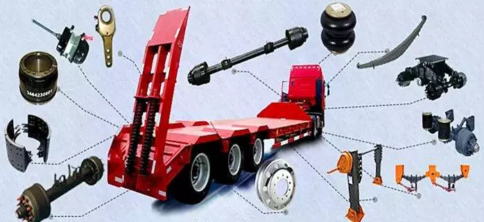
Full-floating axle
A full-floating axle is different from a semi-floating axle in several ways. A semi-floating axle is used for rear wheel drive cars, where it has a bearing mounted in the axle shaft. This axle supports the vehicle’s weight and transmits the drive torque from the transmission to the wheels. However, a semi-floating axle’s load capacity is limited by the size of the axle bearing. A full-floating axle, on the other hand, has the bearing mounted on the outside of the axle tube. The bearing is the only part of the axle that supports the vehicle, and the hub and bearing assembly are held together by a large nut.
The drive axle on a full-floating axle is splined at both ends so that it can easily be removed from the rear of a vehicle without removing the wheel. This type of axle makes it possible to change gears quickly and easily. Because of this, it’s not necessary to remove the wheels and tires in order to replace the axle. Instead, a common tool used to remove the axle from the wheel hub is an axle wrench.
Full-floating axles are more common in heavy-duty vehicles. The ability to carry heavy loads without causing the axle to break is a big advantage to full-floating axles. These axles require less maintenance and require less bends than traditional axles and may even be worth the extra investment if you have a heavy load to carry.
A full-floating axle allows the driver to change a broken axle shaft without having to remove the entire wheel. A full-floating axle will also allow the driver to remove the axle shaft without having to take off the wheel. Full-floating axles are also more durable than semi-floaters, which have weight resting on the axle tubes and housing.
While a full-floating axle is more expensive to manufacture, it is better for heavier vehicles that carry heavy loads. It is better to choose a full-floating axle if you have a heavy load or plan on towing.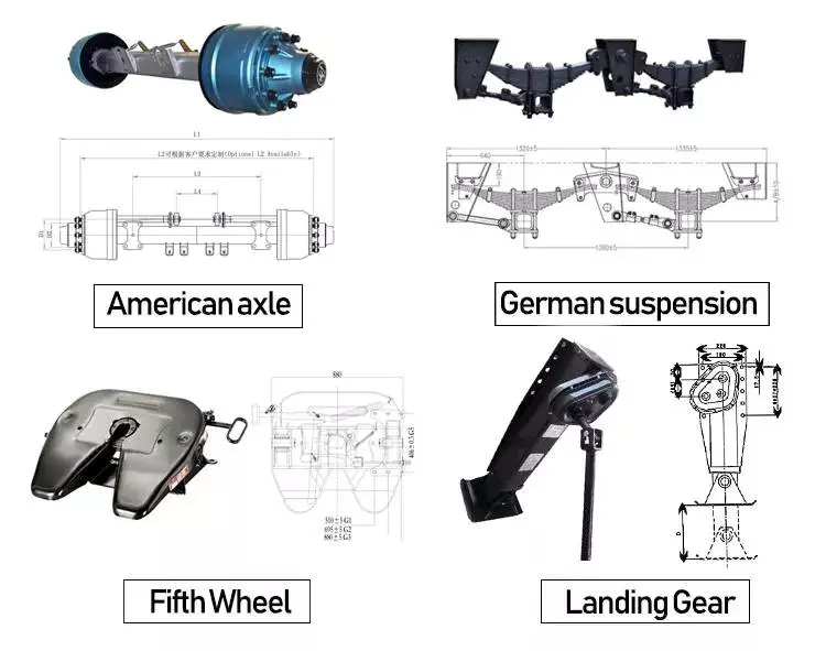
Three-quarter floater
A three-quarter floating axle is a type of floating axle that’s a compromise between the full and semi-floating types. Its bearings are located on the axle casing rather than on the hub, which means that it’s less susceptible to axle breakdown. However, it’s not as robust as a full floating axle.
This design combines the benefits of fully-floating axles with the simplicity of a semi-floating axle. Instead of having multiple wheel bearings, a single wheel bearing is installed in the center of the hub. The hub is then keyed rigidly to the axle shaft, providing a connecting connection and maintaining wheel alignment.
While a full-floating axle is the most common style of truck axle, you may see the three-quarter floater on the side of a pickup. It was common for 3/4-ton Gms to use these axles until the 1980s. Dodge and Ford also used a semi-float axle called a Dana 60. The difference between the two types of axles is the amount of support provided by the axleshaft and hub, and the number of lug nuts on the axleshaft and hub are different.
The three-quarter floater axle drive assembly of the present invention is illustrated in FIG. 1. The axle housing comprises an elongated axle tube 12, a hub member 30, and a hub shaft 16. A hub member 30 is rotatably supported on the axle tube 12 by an anti-friction bearing assembly 42. The axle shaft is retained in place by a domed plate 26.
This axle design has two main advantages. First, it transfers the weight of the vehicle to the axle casing. It also helps transfer the driving torque and side thrust to the wheel. This type of axle also has a differential cross shaft, which limits inward axial movement of the axle shaft.
Dead axle
A Dead axle is a structural component that supports the rear wheel of a vehicle. It can either be straight or angled and is located behind the drive axle. Depending on the vehicle, the dead axle may be steerable. Tag axles are also common on agricultural equipment and certain heavy construction machinery. They are also known as lazy axles because they only contact the ground when a vehicle is carrying a significant load, thus saving tire wear. Dead axles may be rigid or flexible.
Some rear dead axles can also be configured as an air tank. The air is taken in and out of the rear dead axle through the port portions of the rear axle. This can reduce the size of the air tank. For this reason, it is a preferred design for rear dead axles. While most vehicles are equipped with two axles, the rear axle can be used to accommodate cargo.
FIG. 1 is a schematic plan view of a vehicle with two rear axles. The front axle is called the drive axle and the rear dead axle is called the dead axle. These components are located on a truck body frame. There are also battery and fuel tanks. They are used to distribute driving force from the front to rear wheels.
An axle is a crucial component of a vehicle. It transfers power from the engine to the wheels. A live axle is connected to the drive shaft and transmission, while a dead axle receives no direct power. This is the main difference between a live and dead axle. Although a dead axle is not as useful as a live one, it is still essential to understand what drives a car.
Dead axles are used in many vehicles for different purposes. Many large trucks are fitted with several of them for load bearing purposes. They also help distribute weight.
editor by czh 2022-11-30
China wholesaler High Quality CNC Hydraulic Shaft Machine Parts Transmission Shaft Drive Shaft near me shop
Product Description
Organization Profile
Established in 2009, HangZhou CZPT Investing Co., Ltd is a specialist supplier for conveyor elements, found in ZHangZhoug province. We concentrate on giving a assortment of conveyor elements, which includes conveyor tubes, conveyor frames, conveyor rollers, bearing housings and so forth.
With our specialist technologies R&D group, and seasoned good quality management division, our products have been awarded the ISO9001 Good quality Management Method Normal and our main marketplaces are in The usa, Europe, Asia and Australia.
Roller size
Gain:
1.The lifestyle time: Far more than 50000 hours
2. TIR (Overall Indicator Runout)
.5mm (.0197″) for Roll Length -600mm
.8mm (.571″) for Roll Duration 601-1350mm
1.0mm (. 0571 “) for Roll Duration in excess of 1350mm
3.Shaft Float≤0.8mm
4..Samples for testing are accessible.
five. Lower resistance
6. Tiny sustain operate
seven. Higher load ability
eight. Dust evidence & h2o proof
CONVRYOR ROLLER SHAFTS
Conveyor Roller Tube
if you are interesting in our goods or want any further data, remember to really feel totally free to speak to us!
I am hunting forward to your reply.
Greatest regards
Ruth
Web site: hengchuanwin.
HangZhou CZPT Investing CO., LTD
1801 CZPT Constructing, No.268 Xierhuan Road, HangZhou Metropolis, ZHangZhoug Province, China
|
Factory advantage |
Professional and experienced technology team | ||
| All products inspected before shipping with reasonable prices | |||
| Low MOQ and free sample | |||
| We are audited by SGS and passed the ISO9001:2008 certification | |||
|
Industries service |
Industrial machine | ||
| Electronic and communication | |||
| Oil, gas,mining and petroleum | |||
| Construction industry | |||
| Equipment | CNC Machining Center, CNC Lathes, CNC Milling Machines, Punching and drilling machines, Stamping machines | ||
| Precision Processing | CNC machining, CNC turning and milling, laser cutting, drilling, grinding, bending, stamping, welding | ||
###
| No. | Standard Diameter | Length Range (mm) |
Bearing Type Min-Max |
Shell Thickness of Roller | |
| mm | Inch | ||||
| 1 | 63.5 | 2 1/2 | 150-3500 | 203 204 | 3.0mm-4.0mm |
| 2 | 76 | 3 | 150-3500 | 204 | 3.0mm-4.5mm |
| 3 | 89 | 3 1/3 | 150-3500 | 204 205 | 3.0mm-4.5mm |
| 4 | 102 | 4 | 150-3500 | 204 205 206 305 | 3.2mm-4.5mm |
| 5 | 108 | 4 1/4 | 150-3500 | 204 205 206 305 306 | 3.5mm-4.5mm |
| 6 | 114 | 4 1/2 | 150-3500 | 204 205 206 305 306 | 3.5mm-4.5mm |
| 7 | 127 | 5 | 150-3500 | 204 205 206 305 306 | 3.5mm-5.0mm |
| 8 | 133 | 5 1/4 | 150-3500 | 204 205 206 207 305 306 | 3.5mm-5.0mm |
| 9 | 140 | 5 1/2 | 150-3500 | 205 206 207 305 306 307 | 3.5mm-5.0mm |
| 10 | 152 | 6 | 150-3500 | 205 206 207 305 306 307 308 | 4.0mm-5.0mm |
| 11 | 159 | 6 1/4 | 150-3500 | 205 206 207 305 306 307 308 | 4.0mm-5.0mm |
| 12 | 165 | 6 1/2 | 150-3500 | 206 207 305 306 307 308 | 4.5mm-6.0mm |
| 13 | 177.8 | 7 | 150-3500 | 207 306 307 308 309 | 4.5mm-6.0mm |
| 14 | 190.7 | 7 1/2 | 150-3500 | 207 306 307 308 309 310 | 4.5mm-7.0mm |
| 15 | 194 | 7 5/8 | 150-3500 | 207 306 307 308 309 310 | 4.5mm-8.0mm |
| 16 | 219 | 8 5/8 | 150-3500 | 308 309 310 312 | 4.5mm-8.0mm |
###
| We can produce roller shafts and We do customeized |
| Product Size:φ10mm – 70mm |
| Max Length: 3000mm |
| Surface Tolerance: g6 |
| Surface Roughness:0.8mm |
###
| Specification | ASTM A108 AS1443 |
| Steel Grade | Q235B,C1020,C1045(we can also do other steel grade per your requirments) |
| Size | Φ18mm-φ62mm |
| Diameter Tolerance | ISO286-2,H7/H8 |
| Straightness | 2000:1 |
###
| O.D | 63.5-219.1mm |
| W .T | 0.45-20mm |
| Length | 6–12m |
| Standard | SANS 657/3,ASTM 513,AS 1163,BS6323,EN10305 |
| Material | Q235B, S355,S230,C350,E235 etc. |
| Technique | Welded,Seamless |
| Surface | oiled ,galvanized or painted with all kinds of colors according to client’s request. |
| Ends | 1.Plain ends, |
| 2.Threading at both side with plastice caps | |
| 3.Threading at both side with socket/coupling. | |
| 4.Beveled ends, and so on | |
| Packing | 1.Water-proof plastic cloth, |
| 2.Woven bags, | |
| 3.PVC package, | |
| 4.Steel strips in bundles | |
| 5.As your requirment | |
| Usage | 1.For low pressure liquid delivery such as water,gas and oil. |
| 2.For construction | |
| 3.Mechanical equipment | |
| 4.For Furniture | |
| Payment&Trade Terms | 1.Payment : T/T,L/C, D/P, Western union |
| 2.Trade Terms:FOB/CFR/CIF | |
| 3.Minimum quantity of order : 10 MT (10,000KGS) | |
| Delivery Time | 1.Usually,within10-20days after receiving your down payment. |
| 2.According to the order quantity |
###
|
Conveyor Roller Tube |
Specification | SANS657/3,ASTM513,AS1163,BS6323,EN10305 or equivalent international standard. |
| Steel grade | S355/S230,C350,E235,Q235B | |
| Sizes | 63.5mm-219.1mm ect | |
| Ovality tolerance of body | ≤0.4mm(60.3mm-152.4mm) | |
| ≤0.5mm(159MM-168.3mm) | ||
| ≤0.6mm(178mm-219mm) | ||
| Straightness | 2000:1 |
|
Factory advantage |
Professional and experienced technology team | ||
| All products inspected before shipping with reasonable prices | |||
| Low MOQ and free sample | |||
| We are audited by SGS and passed the ISO9001:2008 certification | |||
|
Industries service |
Industrial machine | ||
| Electronic and communication | |||
| Oil, gas,mining and petroleum | |||
| Construction industry | |||
| Equipment | CNC Machining Center, CNC Lathes, CNC Milling Machines, Punching and drilling machines, Stamping machines | ||
| Precision Processing | CNC machining, CNC turning and milling, laser cutting, drilling, grinding, bending, stamping, welding | ||
###
| No. | Standard Diameter | Length Range (mm) |
Bearing Type Min-Max |
Shell Thickness of Roller | |
| mm | Inch | ||||
| 1 | 63.5 | 2 1/2 | 150-3500 | 203 204 | 3.0mm-4.0mm |
| 2 | 76 | 3 | 150-3500 | 204 | 3.0mm-4.5mm |
| 3 | 89 | 3 1/3 | 150-3500 | 204 205 | 3.0mm-4.5mm |
| 4 | 102 | 4 | 150-3500 | 204 205 206 305 | 3.2mm-4.5mm |
| 5 | 108 | 4 1/4 | 150-3500 | 204 205 206 305 306 | 3.5mm-4.5mm |
| 6 | 114 | 4 1/2 | 150-3500 | 204 205 206 305 306 | 3.5mm-4.5mm |
| 7 | 127 | 5 | 150-3500 | 204 205 206 305 306 | 3.5mm-5.0mm |
| 8 | 133 | 5 1/4 | 150-3500 | 204 205 206 207 305 306 | 3.5mm-5.0mm |
| 9 | 140 | 5 1/2 | 150-3500 | 205 206 207 305 306 307 | 3.5mm-5.0mm |
| 10 | 152 | 6 | 150-3500 | 205 206 207 305 306 307 308 | 4.0mm-5.0mm |
| 11 | 159 | 6 1/4 | 150-3500 | 205 206 207 305 306 307 308 | 4.0mm-5.0mm |
| 12 | 165 | 6 1/2 | 150-3500 | 206 207 305 306 307 308 | 4.5mm-6.0mm |
| 13 | 177.8 | 7 | 150-3500 | 207 306 307 308 309 | 4.5mm-6.0mm |
| 14 | 190.7 | 7 1/2 | 150-3500 | 207 306 307 308 309 310 | 4.5mm-7.0mm |
| 15 | 194 | 7 5/8 | 150-3500 | 207 306 307 308 309 310 | 4.5mm-8.0mm |
| 16 | 219 | 8 5/8 | 150-3500 | 308 309 310 312 | 4.5mm-8.0mm |
###
| We can produce roller shafts and We do customeized |
| Product Size:φ10mm – 70mm |
| Max Length: 3000mm |
| Surface Tolerance: g6 |
| Surface Roughness:0.8mm |
###
| Specification | ASTM A108 AS1443 |
| Steel Grade | Q235B,C1020,C1045(we can also do other steel grade per your requirments) |
| Size | Φ18mm-φ62mm |
| Diameter Tolerance | ISO286-2,H7/H8 |
| Straightness | 2000:1 |
###
| O.D | 63.5-219.1mm |
| W .T | 0.45-20mm |
| Length | 6–12m |
| Standard | SANS 657/3,ASTM 513,AS 1163,BS6323,EN10305 |
| Material | Q235B, S355,S230,C350,E235 etc. |
| Technique | Welded,Seamless |
| Surface | oiled ,galvanized or painted with all kinds of colors according to client’s request. |
| Ends | 1.Plain ends, |
| 2.Threading at both side with plastice caps | |
| 3.Threading at both side with socket/coupling. | |
| 4.Beveled ends, and so on | |
| Packing | 1.Water-proof plastic cloth, |
| 2.Woven bags, | |
| 3.PVC package, | |
| 4.Steel strips in bundles | |
| 5.As your requirment | |
| Usage | 1.For low pressure liquid delivery such as water,gas and oil. |
| 2.For construction | |
| 3.Mechanical equipment | |
| 4.For Furniture | |
| Payment&Trade Terms | 1.Payment : T/T,L/C, D/P, Western union |
| 2.Trade Terms:FOB/CFR/CIF | |
| 3.Minimum quantity of order : 10 MT (10,000KGS) | |
| Delivery Time | 1.Usually,within10-20days after receiving your down payment. |
| 2.According to the order quantity |
###
|
Conveyor Roller Tube |
Specification | SANS657/3,ASTM513,AS1163,BS6323,EN10305 or equivalent international standard. |
| Steel grade | S355/S230,C350,E235,Q235B | |
| Sizes | 63.5mm-219.1mm ect | |
| Ovality tolerance of body | ≤0.4mm(60.3mm-152.4mm) | |
| ≤0.5mm(159MM-168.3mm) | ||
| ≤0.6mm(178mm-219mm) | ||
| Straightness | 2000:1 |
Guide to Drive Shafts and U-Joints
If you’re concerned about the performance of your car’s driveshaft, you’re not alone. Many car owners are unaware of the warning signs of a failed driveshaft, but knowing what to look for can help you avoid costly repairs. Here is a brief guide on drive shafts, U-joints and maintenance intervals. Listed below are key points to consider before replacing a vehicle driveshaft.
Symptoms of Driveshaft Failure
Identifying a faulty driveshaft is easy if you’ve ever heard a strange noise from under your car. These sounds are caused by worn U-joints and bearings supporting the drive shaft. When they fail, the drive shafts stop rotating properly, creating a clanking or squeaking sound. When this happens, you may hear noise from the side of the steering wheel or floor.
In addition to noise, a faulty driveshaft can cause your car to swerve in tight corners. It can also lead to suspended bindings that limit overall control. Therefore, you should have these symptoms checked by a mechanic as soon as you notice them. If you notice any of the symptoms above, your next step should be to tow your vehicle to a mechanic. To avoid extra trouble, make sure you’ve taken precautions by checking your car’s oil level.
In addition to these symptoms, you should also look for any noise from the drive shaft. The first thing to look for is the squeak. This was caused by severe damage to the U-joint attached to the drive shaft. In addition to noise, you should also look for rust on the bearing cap seals. In extreme cases, your car can even shudder when accelerating.
Vibration while driving can be an early warning sign of a driveshaft failure. Vibration can be due to worn bushings, stuck sliding yokes, or even springs or bent yokes. Excessive torque can be caused by a worn center bearing or a damaged U-joint. The vehicle may make unusual noises in the chassis system.
If you notice these signs, it’s time to take your car to a mechanic. You should check regularly, especially heavy vehicles. If you’re not sure what’s causing the noise, check your car’s transmission, engine, and rear differential. If you suspect that a driveshaft needs to be replaced, a certified mechanic can replace the driveshaft in your car.
Drive shaft type
Driveshafts are used in many different types of vehicles. These include four-wheel drive, front-engine rear-wheel drive, motorcycles and boats. Each type of drive shaft has its own purpose. Below is an overview of the three most common types of drive shafts:
The driveshaft is a circular, elongated shaft that transmits torque from the engine to the wheels. Drive shafts often contain many joints to compensate for changes in length or angle. Some drive shafts also include connecting shafts and internal constant velocity joints. Some also include torsional dampers, spline joints, and even prismatic joints. The most important thing about the driveshaft is that it plays a vital role in transmitting torque from the engine to the wheels.
The drive shaft needs to be both light and strong to move torque. While steel is the most commonly used material for automotive driveshafts, other materials such as aluminum, composites, and carbon fiber are also commonly used. It all depends on the purpose and size of the vehicle. Precision Manufacturing is a good source for OEM products and OEM driveshafts. So when you’re looking for a new driveshaft, keep these factors in mind when buying.
Cardan joints are another common drive shaft. A universal joint, also known as a U-joint, is a flexible coupling that allows one shaft to drive the other at an angle. This type of drive shaft allows power to be transmitted while the angle of the other shaft is constantly changing. While a gimbal is a good option, it’s not a perfect solution for all applications.
CZPT, Inc. has state-of-the-art machinery to service all types of drive shafts, from small cars to race cars. They serve a variety of needs, including racing, industry and agriculture. Whether you need a new drive shaft or a simple adjustment, the staff at CZPT can meet all your needs. You’ll be back on the road soon!
U-joint
If your car yoke or u-joint shows signs of wear, it’s time to replace them. The easiest way to replace them is to follow the steps below. Use a large flathead screwdriver to test. If you feel any movement, the U-joint is faulty. Also, inspect the bearing caps for damage or rust. If you can’t find the u-joint wrench, try checking with a flashlight.
When inspecting U-joints, make sure they are properly lubricated and lubricated. If the joint is dry or poorly lubricated, it can quickly fail and cause your car to squeak while driving. Another sign that a joint is about to fail is a sudden, excessive whine. Check your u-joints every year or so to make sure they are in proper working order.
Whether your u-joint is sealed or lubricated will depend on the make and model of your vehicle. When your vehicle is off-road, you need to install lubricable U-joints for durability and longevity. A new driveshaft or derailleur will cost more than a U-joint. Also, if you don’t have a good understanding of how to replace them, you may need to do some transmission work on your vehicle.
When replacing the U-joint on the drive shaft, be sure to choose an OEM replacement whenever possible. While you can easily repair or replace the original head, if the u-joint is not lubricated, you may need to replace it. A damaged gimbal joint can cause problems with your car’s transmission or other critical components. Replacing your car’s U-joint early can ensure its long-term performance.
Another option is to use two CV joints on the drive shaft. Using multiple CV joints on the drive shaft helps you in situations where alignment is difficult or operating angles do not match. This type of driveshaft joint is more expensive and complex than a U-joint. The disadvantages of using multiple CV joints are additional length, weight, and reduced operating angle. There are many reasons to use a U-joint on a drive shaft.
maintenance interval
Checking U-joints and slip joints is a critical part of routine maintenance. Most vehicles are equipped with lube fittings on the driveshaft slip joint, which should be checked and lubricated at every oil change. CZPT technicians are well-versed in axles and can easily identify a bad U-joint based on the sound of acceleration or shifting. If not repaired properly, the drive shaft can fall off, requiring expensive repairs.
Oil filters and oil changes are other parts of a vehicle’s mechanical system. To prevent rust, the oil in these parts must be replaced. The same goes for transmission. Your vehicle’s driveshaft should be inspected at least every 60,000 miles. The vehicle’s transmission and clutch should also be checked for wear. Other components that should be checked include PCV valves, oil lines and connections, spark plugs, tire bearings, steering gearboxes and brakes.
If your vehicle has a manual transmission, it is best to have it serviced by CZPT’s East Lexington experts. These services should be performed every two to four years or every 24,000 miles. For best results, refer to the owner’s manual for recommended maintenance intervals. CZPT technicians are experienced in axles and differentials. Regular maintenance of your drivetrain will keep it in good working order.


China Standard CZPT 5 Tons 10 Tons 15 Tons Hydraulic Decoiler with Hot selling
Product Description
hydraulic decoiler
Decoiler –Automatic Hydraulic Decoiling And Feeding Machine:
The decoiler can handle the coil and be capable of feeding the roll into the
Slitting line, and also rewinding partially consumed rolls, so they can be restrapped whilst still on the mandrel, before returning to Coil Storage Facility
For use at a later date.
Line composition:
Entry coil car – Uncoiler – Loop bridge – Side guider – Slitter head – Scrap winder – Loop bridge – Tension station – Recoiler – Exit coil car
Hydraulic system
Electrical system
Technical parameters:
Material: Cold rolled, hot rolled carbon steel, stainless steel, galvanized steel, silicon steel coil, p/o coil, aluminium coil
Width: Up to 2000mm
Thickness: 0.2-2.0mm, 0.3-3.0mm, 1.0-6.0mm, 2.0-12.0mm
Max. Coil weight: 35 tons max
Coil I. D.: 508mm/610mm/760mm
Coil O. D.: 2000mm max
Arbor diameter: 150mm/180mm/220mm
Drive: 380V/50Hz/3PH
Decoiling mode: Over/Under
Direction: According to requirement
Line speed: Up to 120 m/min
Max. Number of slits: 2-30 cuts
Narrowest strip width slit into: 10-25mm
Width cutting accuracy: ± 0.05mm(strip thickness≤ 1), ± 0.1mm(strip thickness>1.5mm)
Slitting burr: 5% of the thickness of material
Installation and training:
A. If buyers visit our factory and check the machine, we will teach you how to install and use the machine, and also train your workers/technician face to face.
B. Without visiting, we will send you user manual and video to teach you to install and operate.
C. If buyer needs our technician to go to your local factory, please arrange board and lodging and other necessary things
Our Services:
1. Customers` Design, Size, Color&Logo are accepted.
2. With15years professional manufacture experience
3. Prompt Delivery&Competitive Price
4. Main markets: Middle East, Europe, North America, Africa, Southeast Asia.
After-sales service:
1. We provide the technical support for whole life of our machines.
2. If buyers need the technician to go abroad, we will arrange the technician,
But the buyers should take all the cost, including visa, roundtripticket etc.
REMARKS:
1 The machine can according to your requirement to set the color
2 Within in 1 year if any parts go broken we will send new ones to replace for free
3 If you want to learn more about the product please login our website or contract to us
| hydraulic Pump Station : | 3KW | |
| Bearing weight: | 10T | |
| feeding roller’s width: | 1350mm | |
| Out line dimension of machine: | 2*5*2.5m | |
| Total weight: | 4.8T | |
If you want to get more information about our equipment ,
Please feel free contact Nancy
The Benefits of Spline Couplings for Disc Brake Mounting Interfaces
Spline couplings are commonly used for securing disc brake mounting interfaces. Spline couplings are often used in high-performance vehicles, aeronautics, and many other applications. However, the mechanical benefits of splines are not immediately obvious. Listed below are the benefits of spline couplings. We’ll discuss what these advantages mean for you. Read on to discover how these couplings work.
Disc brake mounting interfaces are splined
There are 2 common disc brake mounting interfaces – splined and six-bolt. Splined rotors fit on splined hubs; six-bolt rotors will need an adapter to fit on six-bolt hubs. The six-bolt method is easier to maintain and may be preferred by many cyclists. If you’re thinking of installing a disc brake system, it is important to know how to choose the right splined and center lock interfaces.
Aerospace applications
The splines used for spline coupling in aircraft are highly complex. While some previous researches have addressed the design of splines, few publications have tackled the problem of misaligned spline coupling. Nevertheless, the accurate results we obtained were obtained using dedicated simulation tools, which are not commercially available. Nevertheless, such tools can provide a useful reference for our approach. It would be beneficial if designers could use simple tools for evaluating contact pressure peaks. Our analytical approach makes it possible to find answers to such questions.
The design of a spline coupling for aerospace applications must be accurate to minimize weight and prevent failure mechanisms. In addition to weight reduction, it is necessary to minimize fretting fatigue. The pressure distribution on the spline coupling teeth is a significant factor in determining its fretting fatigue. Therefore, we use analytical and experimental methods to examine the contact pressure distribution in the axial direction of spline couplings.
The teeth of a spline coupling can be categorized by the type of engagement they provide. This study investigates the position of resultant contact forces in the teeth of a spline coupling when applied to pitch diameter. Using FEM models, numerical results are generated for nominal and parallel offset misalignments. The axial tooth profile determines the behavior of the coupling component and its ability to resist wear. Angular misalignment is also a concern, causing misalignment.
In order to assess wear damage of a spline coupling, we must take into consideration the impact of fretting on the components. This wear is caused by relative motion between the teeth that engage them. The misalignment may be caused by vibrations, cyclical tooth deflection, or angular misalignment. The result of this analysis may help designers improve their spline coupling designs and develop improved performance.
CZPT polyimide, an abrasion-resistant polymer, is a popular choice for high-temperature spline couplings. This material reduces friction and wear, provides a low friction surface, and has a low wear rate. Furthermore, it offers up to 50 times the life of metal on metal spline connections. For these reasons, it is important to choose the right material for your spline coupling.
High-performance vehicles
A spline coupler is a device used to connect splined shafts. A typical spline coupler resembles a short pipe with splines on either end. There are 2 basic types of spline coupling: single and dual spline. One type attaches to a drive shaft, while the other attaches to the gearbox. While spline couplings are typically used in racing, they’re also used for performance problems.
The key challenge in spline couplings is to determine the optimal dimension of spline joints. This is difficult because no commercial codes allow the simulation of misaligned joints, which can destroy components. This article presents analytical approaches to estimating contact pressures in spline connections. The results are comparable with numerical approaches but require special codes to accurately model the coupling operation. This research highlights several important issues and aims to make the application of spline couplings in high-performance vehicles easier.
The stiffness of spline assemblies can be calculated using tooth-like structures. Such splines can be incorporated into the spline joint to produce global stiffness for torsional vibration analysis. Bearing reactions are calculated for a certain level of misalignment. This information can be used to design bearing dimensions and correct misalignment. There are 3 types of spline couplings.
Major diameter fit splines are made with tightly controlled outside diameters. This close fit provides concentricity transfer from the male to the female spline. The teeth of the male spline usually have chamfered tips and clearance with fillet radii. These splines are often manufactured from billet steel or aluminum. These materials are renowned for their strength and uniform grain created by the forging process. ANSI and DIN design manuals define classes of fit.
Disc brake mounting interfaces
A spline coupling for disc brake mounting interfaces is a type of hub-to-brake-disc mount. It is a highly durable coupling mechanism that reduces heat transfer from the disc to the axle hub. The mounting arrangement also isolates the axle hub from direct contact with the disc. It is also designed to minimize the amount of vehicle downtime and maintenance required to maintain proper alignment.
Disc brakes typically have substantial metal-to-metal contact with axle hub splines. The discs are held in place on the hub by intermediate inserts. This metal-to-metal contact also aids in the transfer of brake heat from the brake disc to the axle hub. Spline coupling for disc brake mounting interfaces comprises a mounting ring that is either a threaded or non-threaded spline.
During drag brake experiments, perforated friction blocks filled with various additive materials are introduced. The materials included include Cu-based powder metallurgy material, a composite material, and a Mn-Cu damping alloy. The filling material affects the braking interface’s wear behavior and friction-induced vibration characteristics. Different filling materials produce different types of wear debris and have different wear evolutions. They also differ in their surface morphology.
Disc brake couplings are usually made of 2 different types. The plain and HD versions are interchangeable. The plain version is the simplest to install, while the HD version has multiple components. The two-piece couplings are often installed at the same time, but with different mounting interfaces. You should make sure to purchase the appropriate coupling for your vehicle. These interfaces are a vital component of your vehicle and must be installed correctly for proper operation.
Disc brakes use disc-to-hub elements that help locate the forces and displace them to the rim. These elements are typically made of stainless steel, which increases the cost of manufacturing the disc brake mounting interface. Despite their benefits, however, the high braking force loads they endure are hard on the materials. Moreover, excessive heat transferred to the intermediate elements can adversely affect the fatigue life and long-term strength of the brake system.
China OEM Widely Used Hydraulic Clamshell Grab for Marine Crane near me factory
Product Description
Widely Used Hydraulic Clamshell Grab For Marine Crane
Discription:
Used for building the base of the foundation pit digging mining, pit mining, gravel and clay, sand, coal loading. Particularly applicable to ditch or restricted space on one side of the excavation and loading. Apply to port ship, train and car.
With double oil cylinders drive and high strength steel production. With big closing force, excellent mining properties,and high work efficiency. Hydraulic turning points according to the customers’ demand, Without hydraulic rotary excavator grab use the oil cylinder or standby line, don’t need to add other hydraulic valve block and line. Rotary hydraulic excavator grab need add another set of hydraulic valve and pipeline to control, oil cylinder makes the piston protective device.
Advantage Hydraulic Grab:
1. The electro hydraulic grab suitable with single hook crane.
2. Electro Hydraulic grab is powerful and efficient in load and discharge different bulk cargo
3. Compare with remote control grab, can handle material quicker
4. Electro Hydraulic clamshell grab can be open and close at any time. More convince to operation it
5. The wire drum protects electric Hydraulic clamshell grab is in from side to side when working, especially when cleaning the vessel
Techinical specifiction:
| Type | Weihgt | Volume | Density | SWL | Size | ||||
| QSEH-1 | (Kg) | m3 | (t) | ||||||
| A | B | C | D | E | |||||
| QSEH400-1 | 560 | 0.4 | 0.4-1.2 | 5 | 1260 | 810 | 1100 | 1350 | 950 |
| QSEH500-1 | 650 | 0.5 | 0.4-1.2 | 6.25 | 1350 | 870 | 1200 | 1460 | 1571 |
| QSEH630-1 | 770 | 0.63 | 0.4-1.2 | 7.6 | 1450 | 930 | 1290 | 1570 | 1100 |
| QSEH800-1 | 920 | 0.8 | 0.4-1.2 | 9.4 | 1510 | 960 | 1340 | 1635 | 1250 |
| QSEH1000-1 | 1070 | 1.0 | 0.4-1.2 | 11.34 | 1620 | 1030 | 1880 | 1760 | 1360 |
| QSEH1250-1 | 1240 | 1.25 | 0.4-1.2 | 13.7 | 1740 | 1100 | 1450 | 1895 | 1450 |
| QSEH1600-1 | 1500 | 1.6 | 0.4-1.2 | 17.1 | 1890 | 1560 | 1690 | 2060 | 1580 |
| QSEH2000-1 | 1740 | 2.0 | 0.4-1.2 | 20.7 | 2030 | 1290 | 1820 | 2220 | 1700 |
| QSEH2500-1 | 2571 | 2.5 | 0.4-1.2 | 25.1 | 2180 | 1385 | 1960 | 2390 | 1830 |
| QSEH3000-1 | 2170 | 3.0 | 0.4-1.2 | 28.8 | 2315 | 1470 | 2085 | 2540 | 1940 |
| QSEH3500-1 | 2260 | 3.5 | 0.4-1.2 | 32.3 | 2430 | 1540 | 2195 | 2670 | 2040 |
| QSEH4200-1 | 2380 | 4.2 | 0.4-1.2 | 37.1 | 2580 | 1635 | 2330 | 2840 | 2170 |
Drawing:
Photos:
Packing:
About us
QSHI supplies different kinds of products. High quality and favorable price.
We’re pleased to get your Inquiry and we will feedback ASAP.
We stick to the principle “Quality First, Service First, Continuous Improvement and Customer Satisfaction” and aim at “Zero Defect Zero Complaint”.
To perfect our service, we provide products with good quality at reasonable price.
Our Service
Being a good adviser and assistant of client, we can help them to get rich and generous returns on their investment.
1.Pre-sale services:
a: Design customized project for clients.
b: Design and manufacture products according to clients special requirement.
c: Train technical personnel for clients.
2.Services during the sale:
a: Help clients to find reasonable freight forwarders ahead of delivery.
b: Help clients to draw solving plans.
3.After-sale services:
a: Assist clients to prepare for the construction scheme.
b: Install and debug equipment.
c: Train the first-line operators.
d: Examine equipment.
e: Take initiative to eliminate the troubles immediately.
f: Provide technical exchanging.
FAQ
ORDER INTRODUCTION:
Pls kindly send us your detailed specifications as follow if you are interested in our grabs.
1 What’s the lifting material?
2 What’s the cubage of the grab?
3 What’s the SWL of your crane?
We will offer you the best suitable grab with best price and quality. These specifications above can make it clear about your requirements.
Thanks very much for your kindly cooperation!
Guide to Drive Shafts and U-Joints
If you’re concerned about the performance of your car’s driveshaft, you’re not alone. Many car owners are unaware of the warning signs of a failed driveshaft, but knowing what to look for can help you avoid costly repairs. Here is a brief guide on drive shafts, U-joints and maintenance intervals. Listed below are key points to consider before replacing a vehicle driveshaft.
Symptoms of Driveshaft Failure
Identifying a faulty driveshaft is easy if you’ve ever heard a strange noise from under your car. These sounds are caused by worn U-joints and bearings supporting the drive shaft. When they fail, the drive shafts stop rotating properly, creating a clanking or squeaking sound. When this happens, you may hear noise from the side of the steering wheel or floor.
In addition to noise, a faulty driveshaft can cause your car to swerve in tight corners. It can also lead to suspended bindings that limit overall control. Therefore, you should have these symptoms checked by a mechanic as soon as you notice them. If you notice any of the symptoms above, your next step should be to tow your vehicle to a mechanic. To avoid extra trouble, make sure you’ve taken precautions by checking your car’s oil level.
In addition to these symptoms, you should also look for any noise from the drive shaft. The first thing to look for is the squeak. This was caused by severe damage to the U-joint attached to the drive shaft. In addition to noise, you should also look for rust on the bearing cap seals. In extreme cases, your car can even shudder when accelerating.
Vibration while driving can be an early warning sign of a driveshaft failure. Vibration can be due to worn bushings, stuck sliding yokes, or even springs or bent yokes. Excessive torque can be caused by a worn center bearing or a damaged U-joint. The vehicle may make unusual noises in the chassis system.
If you notice these signs, it’s time to take your car to a mechanic. You should check regularly, especially heavy vehicles. If you’re not sure what’s causing the noise, check your car’s transmission, engine, and rear differential. If you suspect that a driveshaft needs to be replaced, a certified mechanic can replace the driveshaft in your car.
Drive shaft type
Driveshafts are used in many different types of vehicles. These include four-wheel drive, front-engine rear-wheel drive, motorcycles and boats. Each type of drive shaft has its own purpose. Below is an overview of the 3 most common types of drive shafts:
The driveshaft is a circular, elongated shaft that transmits torque from the engine to the wheels. Drive shafts often contain many joints to compensate for changes in length or angle. Some drive shafts also include connecting shafts and internal constant velocity joints. Some also include torsional dampers, spline joints, and even prismatic joints. The most important thing about the driveshaft is that it plays a vital role in transmitting torque from the engine to the wheels.
The drive shaft needs to be both light and strong to move torque. While steel is the most commonly used material for automotive driveshafts, other materials such as aluminum, composites, and carbon fiber are also commonly used. It all depends on the purpose and size of the vehicle. Precision Manufacturing is a good source for OEM products and OEM driveshafts. So when you’re looking for a new driveshaft, keep these factors in mind when buying.
Cardan joints are another common drive shaft. A universal joint, also known as a U-joint, is a flexible coupling that allows 1 shaft to drive the other at an angle. This type of drive shaft allows power to be transmitted while the angle of the other shaft is constantly changing. While a gimbal is a good option, it’s not a perfect solution for all applications.
CZPT, Inc. has state-of-the-art machinery to service all types of drive shafts, from small cars to race cars. They serve a variety of needs, including racing, industry and agriculture. Whether you need a new drive shaft or a simple adjustment, the staff at CZPT can meet all your needs. You’ll be back on the road soon!
U-joint
If your car yoke or u-joint shows signs of wear, it’s time to replace them. The easiest way to replace them is to follow the steps below. Use a large flathead screwdriver to test. If you feel any movement, the U-joint is faulty. Also, inspect the bearing caps for damage or rust. If you can’t find the u-joint wrench, try checking with a flashlight.
When inspecting U-joints, make sure they are properly lubricated and lubricated. If the joint is dry or poorly lubricated, it can quickly fail and cause your car to squeak while driving. Another sign that a joint is about to fail is a sudden, excessive whine. Check your u-joints every year or so to make sure they are in proper working order.
Whether your u-joint is sealed or lubricated will depend on the make and model of your vehicle. When your vehicle is off-road, you need to install lubricable U-joints for durability and longevity. A new driveshaft or derailleur will cost more than a U-joint. Also, if you don’t have a good understanding of how to replace them, you may need to do some transmission work on your vehicle.
When replacing the U-joint on the drive shaft, be sure to choose an OEM replacement whenever possible. While you can easily repair or replace the original head, if the u-joint is not lubricated, you may need to replace it. A damaged gimbal joint can cause problems with your car’s transmission or other critical components. Replacing your car’s U-joint early can ensure its long-term performance.
Another option is to use 2 CV joints on the drive shaft. Using multiple CV joints on the drive shaft helps you in situations where alignment is difficult or operating angles do not match. This type of driveshaft joint is more expensive and complex than a U-joint. The disadvantages of using multiple CV joints are additional length, weight, and reduced operating angle. There are many reasons to use a U-joint on a drive shaft.
maintenance interval
Checking U-joints and slip joints is a critical part of routine maintenance. Most vehicles are equipped with lube fittings on the driveshaft slip joint, which should be checked and lubricated at every oil change. CZPT technicians are well-versed in axles and can easily identify a bad U-joint based on the sound of acceleration or shifting. If not repaired properly, the drive shaft can fall off, requiring expensive repairs.
Oil filters and oil changes are other parts of a vehicle’s mechanical system. To prevent rust, the oil in these parts must be replaced. The same goes for transmission. Your vehicle’s driveshaft should be inspected at least every 60,000 miles. The vehicle’s transmission and clutch should also be checked for wear. Other components that should be checked include PCV valves, oil lines and connections, spark plugs, tire bearings, steering gearboxes and brakes.
If your vehicle has a manual transmission, it is best to have it serviced by CZPT’s East Lexington experts. These services should be performed every 2 to 4 years or every 24,000 miles. For best results, refer to the owner’s manual for recommended maintenance intervals. CZPT technicians are experienced in axles and differentials. Regular maintenance of your drivetrain will keep it in good working order.
China manufacturer Hydraulic Clamshell Crane Grab with High Quality near me shop
Product Description
Hydraulic Clamshell Crane Grab with High Quality
Discription:
Used for building the base of the foundation pit digging mining, pit mining, gravel and clay, sand, coal loading. Particularly applicable to ditch or restricted space on one side of the excavation and loading. Apply to port ship, train and car.
With double oil cylinders drive and high strength steel production. With big closing force, excellent mining properties,and high work efficiency. Hydraulic turning points according to the customers’ demand, Without hydraulic rotary excavator grab use the oil cylinder or standby line, don’t need to add other hydraulic valve block and line. Rotary hydraulic excavator grab need add another set of hydraulic valve and pipeline to control, oil cylinder makes the piston protective device.
Advantage Hydraulic Grab:
1. The electro hydraulic grab suitable with single hook crane.
2. Electro Hydraulic grab is powerful and efficient in load and discharge different bulk cargo
3. Compare with remote control grab, can handle material quicker
4. Electro Hydraulic clamshell grab can be open and close at any time. More convince to operation it
5. The wire drum protects electric Hydraulic clamshell grab is in from side to side when working, especially when cleaning the vessel
Techinical specifiction:
| Type | Weihgt | Volume | Density | SWL | Size | ||||
| QSEH-1 | (Kg) | m3 | (t) | ||||||
| A | B | C | D | E | |||||
| QSEH400-1 | 560 | 0.4 | 0.4-1.2 | 5 | 1260 | 810 | 1100 | 1350 | 950 |
| QSEH500-1 | 650 | 0.5 | 0.4-1.2 | 6.25 | 1350 | 870 | 1200 | 1460 | 1571 |
| QSEH630-1 | 770 | 0.63 | 0.4-1.2 | 7.6 | 1450 | 930 | 1290 | 1570 | 1100 |
| QSEH800-1 | 920 | 0.8 | 0.4-1.2 | 9.4 | 1510 | 960 | 1340 | 1635 | 1250 |
| QSEH1000-1 | 1070 | 1.0 | 0.4-1.2 | 11.34 | 1620 | 1030 | 1880 | 1760 | 1360 |
| QSEH1250-1 | 1240 | 1.25 | 0.4-1.2 | 13.7 | 1740 | 1100 | 1450 | 1895 | 1450 |
| QSEH1600-1 | 1500 | 1.6 | 0.4-1.2 | 17.1 | 1890 | 1560 | 1690 | 2060 | 1580 |
| QSEH2000-1 | 1740 | 2.0 | 0.4-1.2 | 20.7 | 2030 | 1290 | 1820 | 2220 | 1700 |
| QSEH2500-1 | 2571 | 2.5 | 0.4-1.2 | 25.1 | 2180 | 1385 | 1960 | 2390 | 1830 |
| QSEH3000-1 | 2170 | 3.0 | 0.4-1.2 | 28.8 | 2315 | 1470 | 2085 | 2540 | 1940 |
| QSEH3500-1 | 2260 | 3.5 | 0.4-1.2 | 32.3 | 2430 | 1540 | 2195 | 2670 | 2040 |
| QSEH4200-1 | 2380 | 4.2 | 0.4-1.2 | 37.1 | 2580 | 1635 | 2330 | 2840 | 2170 |
Drawing:
Photos:
Packing:
Related products:
About us
QSHI supplies different kinds of products. High quality and favorable price.
We’re pleased to get your Inquiry and we will feedback ASAP.
We stick to the principle “Quality First, Service First, Continuous Improvement and Customer Satisfaction” and aim at “Zero Defect Zero Complaint”.
To perfect our service, we provide products with good quality at reasonable price.
Our Service
Being a good adviser and assistant of client, we can help them to get rich and generous returns on their investment.
1.Pre-sale services:
a: Design customized project for clients.
b: Design and manufacture products according to clients special requirement.
c: Train technical personnel for clients.
2.Services during the sale:
a: Help clients to find reasonable freight forwarders ahead of delivery.
b: Help clients to draw solving plans.
3.After-sale services:
a: Assist clients to prepare for the construction scheme.
b: Install and debug equipment.
c: Train the first-line operators.
d: Examine equipment.
e: Take initiative to eliminate the troubles immediately.
f: Provide technical exchanging.
FAQ
ORDER INTRODUCTION:
Pls kindly send us your detailed specifications as follow if you are interested in our grabs.
1 What’s the lifting material?
2 What’s the cubage of the grab?
3 What’s the SWL of your crane?
We will offer you the best suitable grab with best price and quality. These specifications above can make it clear about your requirements.
Thanks very much for your kindly cooperation!
The 5 components of an axle, their function and installation
If you’re considering replacing an axle in your vehicle, you should first understand what it is. It is the component that transmits electricity from 1 part to another. Unlike a fixed steering wheel, the axles are movable. The following article will discuss the 5 components of the half shaft, their function and installation. Hopefully you were able to identify the correct axle for your vehicle. Here are some common problems you may encounter along the way.
five components
The 5 components of the shaft are flange, bearing surface, spline teeth, spline pitch and pressure angle. The higher the number of splines, the stronger the shaft. The maximum stress that the shaft can withstand increases with the number of spline teeth and spline pitch. The diameter of the shaft times the cube of the pressure angle and spline pitch determines the maximum stress the shaft can withstand. For extreme load applications, use axles made from SAE 4340 and SAE 1550 materials. In addition to these 2 criteria, spline rolling produces a finer grain structure in the material. Cutting the splines reduces the strength of the shaft by 30% and increases stress.
The asymmetric length of the shaft implies different torsional stiffness. A longer shaft, usually the driver’s side, can handle more twist angles before breaking. When the long axis is intact, the short axis usually fails, but this does not always happen. Some vehicles have short axles that permanently break, causing the same failure rate for both. It would be ideal if both shafts were the same length, they would share the same load.
In addition to the spline pitch, the diameter of the shaft spline is another important factor. The small diameter of a spline is the radius at which it resists twisting. Therefore, the splines must be able to absorb shock loads and shocks while returning to their original shape. To achieve these goals, the spline pitch should be 30 teeth or less, which is standard on Chrysler 8.75-inch and GM 12-bolt axles. However, a Ford 8.8-inch axle may have 28 or 31 tooth splines.
In addition to the CV joints, the axles also include CV joints, which are located on each end of the axle. ACV joints, also known as CV joints, use a special type of bearing called a pinion. This is a nut that meshes with the side gear to ensure proper shaft alignment. If you notice a discrepancy, take your car to a shop and have it repaired immediately.
Function
Axles play several important roles in a vehicle. It transfers power from the transmission to the rear differential gearbox and the wheels. The shaft is usually made of steel with cardan joints at both ends. Shaft Shafts can be stationary or rotating. They are all creatures that can transmit electricity and loads. Here are some of their functions. Read on to learn more about axles. Some of their most important features are listed below.
The rear axle supports the weight of the vehicle and is connected to the front axle through the axle. The rear axle is suspended from the body, frame and axle housing, usually spring loaded, to cushion the vehicle. The driveshaft, also called the propshaft, is located between the rear wheels and the differential. It transfers power from the differential to the drive wheels.
The shaft is made of mild steel or alloy steel. The latter is stronger, more corrosion-resistant and suitable for special environments. Forged for large diameter shafts. The cross section of the shaft is circular. While they don’t transmit torque, they do transmit bending moment. This allows the drive train to rotate. If you’re looking for new axles, it’s worth learning more about how they work.
The shaft consists of 3 distinct parts: the main shaft and the hub. The front axle assembly has a main shaft, while the rear axle is fully floating. Axles are usually made of chrome molybdenum steel. The alloy’s chromium content helps the axle maintain its tensile strength even under extreme conditions. These parts are welded into the axle housing.
Material
The material used to make the axle depends on the purpose of the vehicle. For example, overload shafts are usually made of SAE 4340 or 1550 steel. These steels are high strength low alloy alloys that are resistant to bending and buckling. Chromium alloys, for example, are made from steel and have chromium and molybdenum added to increase their toughness and durability.
The major diameter of the shaft is measured at the tip of the spline teeth, while the minor diameter is measured at the bottom of the groove between the teeth. These 2 diameters must match, otherwise the half shaft will not work properly. It is important to understand that the brittleness of the material should not exceed what is required to withstand normal torque and twisting, otherwise it will become unstable. The material used to make the axles should be strong enough to carry the weight of a heavy truck, but must also be able to withstand torque while still being malleable.
Typically, the shaft is case hardened using an induction process. Heat is applied to the surface of the steel to form martensite and austenite. The shell-core interface transitions from compression to tension, and the peak stress level depends on the process variables used, including heating time, residence time, and hardenability of the steel. Some common materials used for axles are listed below. If you’re not sure which material is best for your axle, consider the following guide.
The axle is the main component of the axle and transmits the transmission motion to the wheels. In addition, they regulate the drive between the rear hub and the differential sun gear. The axle is supported by axle bearings and guided to the path the wheels need to follow. Therefore, they require proper materials, processing techniques and thorough inspection methods to ensure lasting performance. You can start by selecting the material for the shaft.
Choosing the right alloy for the axle is critical. You will want to find an alloy with a low carbon content so it can harden to the desired level. This is an important consideration because the hardenability of the alloy is important to the durability and fatigue life of the axle. By choosing the right alloy, you will be able to minimize these problems and improve the performance of your axle. If you have no other choice, you can always choose an alloy with a higher carbon content, but it will cost you more money.
Install
The process of installing a new shaft is simple. Just loosen the axle nut and remove the set bolt. You may need to tap a few times to get a good seal. After installation, check the shaft at the points marked “A” and “D” to make sure it is in the correct position. Then, press the “F” points on the shaft flange until the points are within 0.002″ of the runout.
Before attempting to install the shaft, check the bearings to make sure they are aligned. Some bearings may have backlash. To determine the amount of differential clearance, use a screwdriver or clamp lever to check. Unless it’s caused by a loose differential case hub, there shouldn’t be any play in the axle bearings. You may need to replace the differential case if the axles are not mounted tightly. Thread adjusters are an option for adjusting drive gear runout. Make sure the dial indicator is mounted on the lead stud and loaded so that the plunger is at right angles to the drive gear.
To install the axle, lift the vehicle with a jack or crane. The safety bracket should be installed under the frame rails. If the vehicle is on a jack, the rear axle should be in the rebound position to ensure working clearance. Label the drive shaft assemblies and reinstall them in their original positions. Once everything is back in place, use a 2-jaw puller to pry the yoke and flange off the shaft.
If you’ve never installed a half shaft before, be sure to read these simple steps to get it right. First, check the bearing surfaces to make sure they are clean and undamaged. Replace them if they look battered or dented. Next, remove the seal attached to the bushing hole. Make sure the shaft is installed correctly and the bearing surfaces are level. After completing the installation process, you may need to replace the bearing seals.
China Professional Mobile Portable Hydraulic Aerial Lifts/Sing Mast Aluminum Lift Platform Xg0807dcw Xg1012HD with 8m 10m Lifting Height with Hot selling
Product Description
New aerial work platform developed by X has the work height at 10m, the vehicle width at 1.19m, the rated load at 450kg, max. gradeability at 25%. This vehicle features compact structure, advanced performance, completed safety devices, specially suitable for construction. In addition. It is free of any pollution, with steady lifting / lowering, easy control and maintenance. Therefore, this kind of platforms are widely applied to warehouses, factories, airports, and train stations, especially the narrow work sites.
Advantages and features:
* Effective and energy-saving electric-drive system features zero emission and low noise, together with the traceless tires, enabling this machine easily to work in enclosed environments such as office building, hospitals and schools and minimizing the effect on environment.
* Active protective mechanism such as pothole protective mechanism and the self-developed safety control system feature the humanized design and the rich options, meeting the customer needing for safety, reliability and intelligence.
* Narrow- structure design enables the complete vehicle to easily pass through a single gateway; foldable fence could make the transportation easier
* “Zero Turning Radius “is unique and enable machine to corner in narrow room.
* Max. payload at 450kg, leading the industry. Maximum traveling speed 3.2km/h and 25% gradeability make the driving easier.
Product Paramenters
|
Item |
Unit |
Parameter |
||
|
Dimension of machine |
Length (without ladder) |
mm |
2477(2267) |
|
|
Width |
mm |
1190 |
||
|
Height(platform folded) |
mm |
2355(1805) |
||
|
Wheelbase |
mm |
1877 |
||
|
Min. ground clearance (Pit protector ascending/descending) |
mm |
100/20 |
||
|
Max. height of platform |
m |
8 |
||
|
Max. working height |
m |
10 |
||
|
Minimum turning radius (inner wheel/outer wheel) |
m |
0/2.3 |
||
|
Rated load |
kg |
450 |
||
|
Payload of extended platform |
kg |
115 |
||
|
Lifting time |
s |
29-40 |
||
|
Lowering time |
s |
34-45 |
||
|
Drive speed(lowered) |
km/h |
3.2 |
||
|
Drive speed(elevated) |
km/h |
0.8 |
||
|
Max. gradeability |
% |
25 |
||
|
Tilt warning angle (side/forward and backward) |
° |
1.5/3 |
||
|
Lifting /traveling motor |
Model |
– |
– |
|
|
Rated power |
kW |
3.3 |
||
|
Manufacturer |
– |
– |
||
|
Battery |
v/Ah |
4×6/225 |
||
|
Tire models |
– |
Traceless and solid/381×127 |
||
An Overview of Worm Shafts and Gears
This article provides an overview of worm shafts and gears, including the type of toothing and deflection they experience. Other topics covered include the use of aluminum versus bronze worm shafts, calculating worm shaft deflection and lubrication. A thorough understanding of these issues will help you to design better gearboxes and other worm gear mechanisms. For further information, please visit the related websites. We also hope that you will find this article informative.
Double throat worm gears
The pitch diameter of a worm and the pitch of its worm wheel must be equal. The 2 types of worm gears have the same pitch diameter, but the difference lies in their axial and circular pitches. The pitch diameter is the distance between the worm’s teeth along its axis and the pitch diameter of the larger gear. Worms are made with left-handed or right-handed threads. The lead of the worm is the distance a point on the thread travels during 1 revolution of the worm gear. The backlash measurement should be made in a few different places on the gear wheel, as a large amount of backlash implies tooth spacing.
A double-throat worm gear is designed for high-load applications. It provides the tightest connection between worm and gear. It is crucial to mount a worm gear assembly correctly. The keyway design requires several points of contact, which block shaft rotation and help transfer torque to the gear. After determining the location of the keyway, a hole is drilled into the hub, which is then screwed into the gear.
The dual-threaded design of worm gears allows them to withstand heavy loads without slipping or tearing out of the worm. A double-throat worm gear provides the tightest connection between worm and gear, and is therefore ideal for hoisting applications. The self-locking nature of the worm gear is another advantage. If the worm gears are designed well, they are excellent for reducing speeds, as they are self-locking.
When choosing a worm, the number of threads that a worm has is critical. Thread starts determine the reduction ratio of a pair, so the higher the threads, the greater the ratio. The same is true for the worm helix angles, which can be one, two, or 3 threads long. This varies between a single thread and a double-throat worm gear, and it is crucial to consider the helix angle when selecting a worm.
Double-throat worm gears differ in their profile from the actual gear. Double-throat worm gears are especially useful in applications where noise is an issue. In addition to their low noise, worm gears can absorb shock loads. A double-throat worm gear is also a popular choice for many different types of applications. These gears are also commonly used for hoisting equipment. Its tooth profile is different from that of the actual gear.
Bronze or aluminum worm shafts
When selecting a worm, a few things should be kept in mind. The material of the shaft should be either bronze or aluminum. The worm itself is the primary component, but there are also addendum gears that are available. The total number of teeth on both the worm and the addendum gear should be greater than 40. The axial pitch of the worm needs to match the circular pitch of the larger gear.
The most common material used for worm gears is bronze because of its desirable mechanical properties. Bronze is a broad term referring to various copper alloys, including copper-nickel and copper-aluminum. Bronze is most commonly created by alloying copper with tin and aluminum. In some cases, this combination creates brass, which is a similar metal to bronze. The latter is less expensive and suitable for light loads.
There are many benefits to bronze worm gears. They are strong and durable, and they offer excellent wear-resistance. In contrast to steel worms, bronze worm gears are quieter than their counterparts. They also require no lubrication and are corrosion-resistant. Bronze worms are popular with small, light-weight machines, as they are easy to maintain. You can read more about worm gears in CZPT’s CZPT.
Although bronze or aluminum worm shafts are the most common, both materials are equally suitable for a variety of applications. A bronze shaft is often called bronze but may actually be brass. Historically, worm gears were made of SAE 65 gear bronze. However, newer materials have been introduced. SAE 65 gear bronze (UNS C90700) remains the preferred material. For high-volume applications, the material savings can be considerable.
Both types of worms are essentially the same in size and shape, but the lead on the left and right tooth surfaces can vary. This allows for precise adjustment of the backlash on a worm without changing the center distance between the worm gear. The different sizes of worms also make them easier to manufacture and maintain. But if you want an especially small worm for an industrial application, you should consider bronze or aluminum.
Calculation of worm shaft deflection
The centre-line distance of a worm gear and the number of worm teeth play a crucial role in the deflection of the rotor. These parameters should be entered into the tool in the same units as the main calculation. The selected variant is then transferred to the main calculation. The deflection of the worm gear can be calculated from the angle at which the worm teeth shrink. The following calculation is helpful for designing a worm gear.
Worm gears are widely used in industrial applications due to their high transmittable torques and large gear ratios. Their hard/soft material combination makes them ideally suited for a wide range of applications. The worm shaft is typically made of case-hardened steel, and the worm wheel is fabricated from a copper-tin-bronze alloy. In most cases, the wheel is the area of contact with the gear. Worm gears also have a low deflection, as high shaft deflection can affect the transmission accuracy and increase wear.
Another method for determining worm shaft deflection is to use the tooth-dependent bending stiffness of a worm gear’s toothing. By calculating the stiffness of the individual sections of a worm shaft, the stiffness of the entire worm can be determined. The approximate tooth area is shown in figure 5.
Another way to calculate worm shaft deflection is by using the FEM method. The simulation tool uses an analytical model of the worm gear shaft to determine the deflection of the worm. It is based on a two-dimensional model, which is more suitable for simulation. Then, you need to input the worm gear’s pitch angle and the toothing to calculate the maximum deflection.
Lubrication of worm shafts
In order to protect the gears, worm drives require lubricants that offer excellent anti-wear protection, high oxidation resistance, and low friction. While mineral oil lubricants are widely used, synthetic base oils have better performance characteristics and lower operating temperatures. The Arrhenius Rate Rule states that chemical reactions double every 10 degrees C. Synthetic lubricants are the best choice for these applications.
Synthetics and compounded mineral oils are the most popular lubricants for worm gears. These oils are formulated with mineral basestock and 4 to 6 percent synthetic fatty acid. Surface-active additives give compounded gear oils outstanding lubricity and prevent sliding wear. These oils are suited for high-speed applications, including worm gears. However, synthetic oil has the disadvantage of being incompatible with polycarbonate and some paints.
Synthetic lubricants are expensive, but they can increase worm gear efficiency and operating life. Synthetic lubricants typically fall into 2 categories: PAO synthetic oils and EP synthetic oils. The latter has a higher viscosity index and can be used at a range of temperatures. Synthetic lubricants often contain anti-wear additives and EP (anti-wear).
Worm gears are frequently mounted over or under the gearbox. The proper lubrication is essential to ensure the correct mounting and operation. Oftentimes, inadequate lubrication can cause the unit to fail sooner than expected. Because of this, a technician may not make a connection between the lack of lube and the failure of the unit. It is important to follow the manufacturer’s recommendations and use high-quality lubricant for your gearbox.
Worm drives reduce backlash by minimizing the play between gear teeth. Backlash can cause damage if unbalanced forces are introduced. Worm drives are lightweight and durable because they have minimal moving parts. In addition, worm drives are low-noise and vibration. In addition, their sliding motion scrapes away excess lubricant. The constant sliding action generates a high amount of heat, which is why superior lubrication is critical.
Oils with a high film strength and excellent adhesion are ideal for lubrication of worm gears. Some of these oils contain sulfur, which can etch a bronze gear. In order to avoid this, it is imperative to use a lubricant that has high film strength and prevents asperities from welding. The ideal lubricant for worm gears is 1 that provides excellent film strength and does not contain sulfur.
China supplier Hydraulic Vertical Electric Rail Warehouse Goods Lift with Free Design Custom
Product Description
Hydraulic Vertical Electric Rail Warehouse Goods Lift
Welcome to Moral lift !!!
We are professional manufacturer of LIFT TABLE with good quality and low price. We are adhering to our priciple of ” Put quality first and treat cudstomers as supremacy; People-oriented, honesty comes first”. We have good quality products, prompt telephone services and skilled maimtenance personnel for our customers.
Look forward to having opportunity to cooperate with all of you around the world!
Description:
Vertical lift–Lead rail hydraulic lifting platform is used for transfer cargo between different floors. Self-height is about 150-300mm. This platform can install on the ground directly or make 1 pit. Hydraulic drive, steady working and simple operate.
This machine provide fast, efficient, convenient and safe access to or from mezzanines, balconies, basements, and between levels in multiple story buildings. They can be installed for through-floor, interior or exterior applications.The principle components of machine include CZPT columns, carriage and a mechanical or hydraulic actuating mechanism.
We offer the most complete line of machine from mechanical to hydraulic to fully automatic, customized systems for automated manufacturing and warehousing operations. machine are available in capacities from 100kg. to 100,000kg.
Main Feature:
chain lifting platform features lifting the goods through the different floors.
chain lifting platform—-hydraulic driven and lift by chain .
special lifting chain and have long use life.
the close height is low so don not need pit installation.
closed type structure ,safe and easy to clean.
steady up and down
Friendship Tips:
The lift mainly produce according to customers special requirement, so when you send a inquiry, please kindly send the below information to us:
1). Load capacity:____kg
2.) Lift height:_____m
3.) Table size:__(L)×__(W) m
Our Service:
1.Good service
We assure you reply the email within 24 hours.
We assure you 12 mouth quality warranty time.
During the warranty period we guarantee to supply free replacement parts to any defective of our product.
2.Keeping innovations
We welcome every recommendation and opinion from you and make progress together with you.
We can design a new machine as your requirements,until to your satisfaction.
FAQ:
1. Are you a trader or manufacturer?
We are experienced, licensed manufacturer. We may offer low price and more direct service.
2. Warranty?
Main structure and machinery warranty for 12 months after delivery port.
3. How to deliver?
Based on the destination, it can transport by ship, by truck, or by railway, etc. By ship, our product is designed to fit in 40’HQ container or 20′ GP container, which saves shipping cost.
4. Do you accept OEM or ODM?
Yes.
5. How do we do installation? Can you send technician for assistance?
Operation manual and foundation drawing will teach you step-by-step. You may employ local engineering team or use your own team. Also, we can arrange technician to instruct installation, and to train your workers how to maintain. But the cost will be bear by buyer, including round-up air ticket, food, visa, accommodation, extra salary after agreed working days, etc.
6. Do we need to purchase extra easy wear parts?
We strongly recommend you purchase some along with the equipment, which saves time and transportation cost, when years later you need to change some easy wear parts, your project wouldn’t be delayed.
7. If we want to be your agent?
Agent, distributor, dealer, and sole agent, is highly wanted. We need local people to develop market for us, especially those with experienced after-sales service team. We will offer competitive agent price, market promotion support, technical support, and staff training. The number of agent is limited in certain area, so as to protect your interest.
Analytical Approaches to Estimating Contact Pressures in Spline Couplings
A spline coupling is a type of mechanical connection between 2 rotating shafts. It consists of 2 parts – a coupler and a coupling. Both parts have teeth which engage and transfer loads. However, spline couplings are typically over-dimensioned, which makes them susceptible to fatigue and static behavior. Wear phenomena can also cause the coupling to fail. For this reason, proper spline coupling design is essential for achieving optimum performance.
Modeling a spline coupling
Spline couplings are becoming increasingly popular in the aerospace industry, but they operate in a slightly misaligned state, causing both vibrations and damage to the contact surfaces. To solve this problem, this article offers analytical approaches for estimating the contact pressures in a spline coupling. Specifically, this article compares analytical approaches with pure numerical approaches to demonstrate the benefits of an analytical approach.
To model a spline coupling, first you create the knowledge base for the spline coupling. The knowledge base includes a large number of possible specification values, which are related to each other. If you modify 1 specification, it may lead to a warning for violating another. To make the design valid, you must create a spline coupling model that meets the specified specification values.
After you have modeled the geometry, you must enter the contact pressures of the 2 spline couplings. Then, you need to determine the position of the pitch circle of the spline. In Figure 2, the centre of the male coupling is superposed to that of the female spline. Then, you need to make sure that the alignment meshing distance of the 2 splines is the same.
Once you have the data you need to create a spline coupling model, you can begin by entering the specifications for the interface design. Once you have this data, you need to choose whether to optimize the internal spline or the external spline. You’ll also need to specify the tooth friction coefficient, which is used to determine the stresses in the spline coupling model 20. You should also enter the pilot clearance, which is the clearance between the tip 186 of a tooth 32 on 1 spline and the feature on the mating spline.
After you have entered the desired specifications for the external spline, you can enter the parameters for the internal spline. For example, you can enter the outer diameter limit 154 of the major snap 54 and the minor snap 56 of the internal spline. The values of these parameters are displayed in color-coded boxes on the Spline Inputs and Configuration GUI screen 80. Once the parameters are entered, you’ll be presented with a geometric representation of the spline coupling model 20.
Creating a spline coupling model 20
The spline coupling model 20 is created by a product model software program 10. The software validates the spline coupling model against a knowledge base of configuration-dependent specification constraints and relationships. This report is then input to the ANSYS stress analyzer program. It lists the spline coupling model 20’s geometric configurations and specification values for each feature. The spline coupling model 20 is automatically recreated every time the configuration or performance specifications of the spline coupling model 20 are modified.
The spline coupling model 20 can be configured using the product model software program 10. A user specifies the axial length of the spline stack, which may be zero, or a fixed length. The user also enters a radial mating face 148, if any, and selects a pilot clearance specification value of 14.5 degrees or 30 degrees.
A user can then use the mouse 110 to modify the spline coupling model 20. The spline coupling knowledge base contains a large number of possible specification values and the spline coupling design rule. If the user tries to change a spline coupling model, the model will show a warning about a violation of another specification. In some cases, the modification may invalidate the design.
In the spline coupling model 20, the user enters additional performance requirement specifications. The user chooses the locations where maximum torque is transferred for the internal and external splines 38 and 40. The maximum torque transfer location is determined by the attachment configuration of the hardware to the shafts. Once this is selected, the user can click “Next” to save the model. A preview of the spline coupling model 20 is displayed.
The model 20 is a representation of a spline coupling. The spline specifications are entered in the order and arrangement as specified on the spline coupling model 20 GUI screen. Once the spline coupling specifications are entered, the product model software program 10 will incorporate them into the spline coupling model 20. This is the last step in spline coupling model creation.
Analysing a spline coupling model 20
An analysis of a spline coupling model consists of inputting its configuration and performance specifications. These specifications may be generated from another computer program. The product model software program 10 then uses its internal knowledge base of configuration dependent specification relationships and constraints to create a valid three-dimensional parametric model 20. This model contains information describing the number and types of spline teeth 32, snaps 34, and shoulder 36.
When you are analysing a spline coupling, the software program 10 will include default values for various specifications. The spline coupling model 20 comprises an internal spline 38 and an external spline 40. Each of the splines includes its own set of parameters, such as its depth, width, length, and radii. The external spline 40 will also contain its own set of parameters, such as its orientation.
Upon selecting these parameters, the software program will perform various analyses on the spline coupling model 20. The software program 10 calculates the nominal and maximal tooth bearing stresses and fatigue life of a spline coupling. It will also determine the difference in torsional windup between an internal and an external spline. The output file from the analysis will be a report file containing model configuration and specification data. The output file may also be used by other computer programs for further analysis.
Once these parameters are set, the user enters the design criteria for the spline coupling model 20. In this step, the user specifies the locations of maximum torque transfer for both the external and internal spline 38. The maximum torque transfer location depends on the configuration of the hardware attached to the shafts. The user may enter up to 4 different performance requirement specifications for each spline.
The results of the analysis show that there are 2 phases of spline coupling. The first phase shows a large increase in stress and vibration. The second phase shows a decline in both stress and vibration levels. The third stage shows a constant meshing force between 300N and 320N. This behavior continues for a longer period of time, until the final stage engages with the surface.
Misalignment of a spline coupling
A study aimed to investigate the position of the resultant contact force in a spline coupling engaging teeth under a steady torque and rotating misalignment. The study used numerical methods based on Finite Element Method (FEM) models. It produced numerical results for nominal conditions and parallel offset misalignment. The study considered 2 levels of misalignment – 0.02 mm and 0.08 mm – with different loading levels.
The results showed that the misalignment between the splines and rotors causes a change in the meshing force of the spline-rotor coupling system. Its dynamics is governed by the meshing force of splines. The meshing force of a misaligned spline coupling is related to the rotor-spline coupling system parameters, the transmitting torque, and the dynamic vibration displacement.
Despite the lack of precise measurements, the misalignment of splines is a common problem. This problem is compounded by the fact that splines usually feature backlash. This backlash is the result of the misaligned spline. The authors analyzed several splines, varying pitch diameters, and length/diameter ratios.
A spline coupling is a two-dimensional mechanical system, which has positive backlash. The spline coupling is comprised of a hub and shaft, and has tip-to-root clearances that are larger than the backlash. A form-clearance is sufficient to prevent tip-to-root fillet contact. The torque on the splines is transmitted via friction.
When a spline coupling is misaligned, a torque-biased thrust force is generated. In such a situation, the force can exceed the torque, causing the component to lose its alignment. The two-way transmission of torque and thrust is modeled analytically in the present study. The analytical approach provides solutions that can be integrated into the design process. So, the next time you are faced with a misaligned spline coupling problem, make sure to use an analytical approach!
In this study, the spline coupling is analyzed under nominal conditions without a parallel offset misalignment. The stiffness values obtained are the percentage difference between the nominal pitch diameter and load application diameter. Moreover, the maximum percentage difference in the measured pitch diameter is 1.60% under a torque of 5000 N*m. The other parameter, the pitch angle, is taken into consideration in the calculation.