Bubble wrap/pearl wool + Carton or Pallet; As per customized specifications
Sea Port
ZheJiang port/HangZhou port
Payment terms
T/T in advance, PayPal or Western Union is acceptable.
Trade Terms
EXW, FOB, CIF, As per customer’s request
Drawing format
PDF, DWG, CAD, DXF, STEP, IGS etc
Note:
All cnc machining parts are custom made according to customer’s design drawings or exsiting
samples, we have no any ready parts in stock for sales.
If you have any cnc machining parts need to be made, please feel free to send your kind
drawings/samples to us.
Products Display :
About Us :
1. We are ODM&OEM, design according to your drawing. 2. Rich experience and good technology support( have engineers with more than 20 years experience). 3. we are Manufacturer 4. Low MOQ is accepted. 5. 100% inspection before delivery. 6. Competitive price with high quality. 7. Convenient transportation ( HangZhou, ZheJiang …)
1. Factory directly supply 2. Many years manufacture experience 3. Competitive and reasonable price 4. OEM service, we can do as your drawings or samples 5. Quality Guarantee 6. Good after-sale service 7. Timely delivery 8. High-tech CNC Machines 9. Independent Engineering Department 10.Kinds of surface treatment—Zinc Plating, Powder Coating, Anodizing, Chrome Plate, RoHs etc as
All kinds of CNC machining parts, sheet metal parts and machinery parts are available. OEM/ODM metal CNC parts, metal machining parts with laser cutting, die stamping, CNC machining, CNC shearing, Welding, Bending & metal fabrications, welding robots etc.
If you are interested in any of our products, please click your mouse and send email to us by below
approach. We will reply to you winthin 12 hours.
/* January 22, 2571 19:08:37 */!function(){function s(e,r){var a,o={};try{e&&e.split(“,”).forEach(function(e,t){e&&(a=e.match(/(.*?):(.*)$/))&&1
After-sales Service:
Yes
Warranty:
12 Months
Condition:
New
Certification:
RoHS, ISO9001
Standard:
DIN, ASTM, GOST, GB, JIS, ANSI, BS
Customized:
Customized
Samples:
US$ 5/Piece 1 Piece(Min.Order)
|
Request Sample
Customization:
Available
|
Customized Request
What are the safety considerations when working with axles, especially during repairs?
Working with axles, especially during repairs, requires careful attention to safety to prevent accidents and injuries. Here are some important safety considerations to keep in mind when working with axles:
1. Personal Protective Equipment (PPE):
Wear appropriate personal protective equipment, including safety goggles, gloves, and steel-toed boots. PPE helps protect against potential hazards such as flying debris, sharp edges, and accidental contact with heavy components.
2. Vehicle Stability:
Ensure that the vehicle is on a stable and level surface before working on the axles. Engage the parking brake and use wheel chocks to prevent unintended vehicle movement. The stability of the vehicle is crucial to maintain a safe working environment.
3. Lifting and Support:
Use proper lifting equipment, such as hydraulic jacks or vehicle lifts, to raise the vehicle safely. Follow the manufacturer’s guidelines for lifting points and weight capacities. Once the vehicle is lifted, support it securely with jack stands or other appropriate supports to prevent it from falling or shifting during repairs.
4. Lockout/Tagout:
If the repair work involves disconnecting or removing any electrical or mechanical components that could cause the axle or wheels to move, follow lockout/tagout procedures. This involves locking and tagging out the power source, so it cannot be accidentally energized while work is being performed.
5. Proper Tools and Equipment:
Use the correct tools and equipment for the job. Using improper tools or makeshift methods can lead to accidents and damage to the axle or surrounding components. Follow the manufacturer’s instructions and recommended procedures for disassembling, repairing, and reassembling the axle.
6. Proper Torque and Tightening:
When reassembling the axle components, use a torque wrench to ensure that fasteners are tightened to the manufacturer’s specifications. Over-tightening or under-tightening can lead to component failure or damage. Follow the recommended torque values provided by the vehicle manufacturer.
7. Safe Handling of Heavy Components:
Axle components can be heavy and cumbersome. Use appropriate lifting techniques and equipment, such as hoists or lifting straps, to safely handle heavy axle parts. Avoid lifting heavy components alone whenever possible and ask for assistance when needed.
8. Proper Disposal of Fluids and Waste:
If the repair involves draining fluids from the axle, such as differential oil, ensure proper disposal according to local regulations. Use appropriate containers to collect and store fluids and dispose of them at authorized collection points.
9. Training and Experience:
Working with axles requires knowledge and experience. If you are unfamiliar with axle repairs, consider seeking assistance from a qualified mechanic or technician who has the necessary training and expertise. If you decide to perform the repairs yourself, ensure that you have the appropriate knowledge and skills to carry out the task safely.
By following these safety considerations, you can help minimize the risk of accidents, injuries, and damage when working with axles, ensuring a safe working environment for yourself and others involved in the repair process.
Can you recommend axle manufacturers known for durability and reliability?
When it comes to choosing axle manufacturers known for durability and reliability, there are several reputable companies in the automotive industry. While individual experiences and preferences may vary, the following axle manufacturers have a track record of producing high-quality products:
1. Dana Holding Corporation: Dana is a well-known manufacturer of axles, drivetrain components, and sealing solutions. They supply axles to various automotive manufacturers and have a reputation for producing durable and reliable products. Dana axles are commonly found in trucks, SUVs, and off-road vehicles.
2. AAM (American Axle & Manufacturing): AAM is a leading manufacturer of driveline and drivetrain components, including axles. They supply axles to both OEMs (Original Equipment Manufacturers) and the aftermarket. AAM axles are known for their durability and are often found in trucks, SUVs, and performance vehicles.
3. GKN Automotive: GKN Automotive is a global supplier of driveline systems, including axles. They have a strong reputation for producing high-quality and reliable axles for a wide range of vehicles. GKN Automotive supplies axles to various automakers and is recognized for their technological advancements in the field.
4. Meritor: Meritor is a manufacturer of axles, brakes, and other drivetrain components for commercial vehicles. They are known for their robust and reliable axle products that cater to heavy-duty applications in the commercial trucking industry.
5. Spicer (Dana Spicer): Spicer, a division of Dana Holding Corporation, specializes in manufacturing drivetrain components, including axles. Spicer axles are widely used in off-road vehicles, trucks, and SUVs. They are known for their durability and ability to withstand demanding off-road conditions.
6. Timken: Timken is a trusted manufacturer of bearings, seals, and other mechanical power transmission products. While they are primarily known for their bearings, they also produce high-quality axle components used in various applications, including automotive axles.
It’s important to note that the availability of specific axle manufacturers may vary depending on the region and the specific vehicle make and model. Additionally, different vehicles may come equipped with axles from different manufacturers as per the OEM’s selection and sourcing decisions.
When considering axle replacements or upgrades, it is advisable to consult with automotive experts, including mechanics or dealerships familiar with your vehicle, to ensure compatibility and make informed decisions based on your specific needs and requirements.
What are the factors to consider when choosing an axle for a custom-built vehicle?
Choosing the right axle for a custom-built vehicle is crucial for ensuring optimal performance, durability, and safety. Here are several key factors to consider when selecting an axle for a custom-built vehicle:
Vehicle Type and Intended Use:
Consider the type of vehicle you are building and its intended use. Factors such as vehicle weight, power output, terrain (on-road or off-road), towing capacity, and payload requirements will influence the axle selection. Off-road vehicles may require axles with higher strength and durability, while performance-oriented vehicles may benefit from axles that can handle increased power and torque.
Axle Type:
Choose the appropriate axle type based on your vehicle’s drivetrain configuration. Common axle types include solid axles (live axles) and independent axles. Solid axles are often used in heavy-duty applications and off-road vehicles due to their robustness and ability to handle high loads. Independent axles offer improved ride quality and handling characteristics but may have lower load-carrying capacities.
Weight Capacity:
Determine the required weight capacity of the axle based on the vehicle’s weight and intended payload. It’s crucial to select an axle that can handle the anticipated loads without exceeding its weight rating. Consider factors such as cargo, passengers, and accessories that may contribute to the overall weight.
Axle Ratio:
Choose an axle ratio that matches your vehicle’s powertrain and desired performance characteristics. The axle ratio affects the torque multiplication between the engine and wheels, influencing acceleration, towing capability, and fuel efficiency. Higher axle ratios provide more torque multiplication for improved low-end power but may sacrifice top-end speed.
Braking System Compatibility:
Ensure that the chosen axle is compatible with your vehicle’s braking system. Consider factors such as the axle’s mounting provisions for brake calipers, rotor size compatibility, and the need for an anti-lock braking system (ABS) if required.
Suspension Compatibility:
Consider the compatibility of the chosen axle with your vehicle’s suspension system. Factors such as axle mounting points, suspension geometry, and overall ride height should be taken into account. Ensure that the axle can be properly integrated with your chosen suspension components and that it provides sufficient ground clearance for your specific application.
Aftermarket Support:
Consider the availability of aftermarket support for the chosen axle. This includes access to replacement parts, upgrade options, and technical expertise. A robust aftermarket support network can be beneficial for future maintenance, repairs, and customization needs.
Budget:
Set a realistic budget for the axle selection, keeping in mind that high-performance or specialized axles may come at a higher cost. Balance your requirements with your budget to find the best axle option that meets your needs without exceeding your financial limitations.
When choosing an axle for a custom-built vehicle, it’s recommended to consult with knowledgeable professionals, experienced builders, or reputable axle manufacturers. They can provide valuable guidance, assist in understanding technical specifications, and help you select the most suitable axle for your specific custom vehicle project.
Calendar year: 2011- Product: CM10 Box Car Fitment: Changan Product Amount: LLSEL-twenty Auto Make: electrical automobile OE NO.: 00005716 Guarantee: twelve Months Application: Electric Car Motor Electricity: 20kw Material: Metal Ratio: 18:1 Size: 1450mm Bodyweight(kg): 100 Motor Speed: 6000r/min OEM: Avaible brake dimension: 250 Packaging Details: wooden box Port: ZheJiang
Specification
10kw motor driving axle Specification:
axle load
4000kg
axle size
1620mm
axle bolts sample for rim
standard is 5-M14-139.7can be 4-M12-114.3
axle tube diameter
80mm
gearbox reduction ratio
13/one
max input torque
300NM
max input pace
6500rpm
matched motor power
20kw-30kw
application
electric bus or truck or van
axle input spline
24 teeth
Packing & MR115 modest ballbearing 5x11x3.5mm maquinas herramienta miniatura SMR115 open Shipping the axle is packaged by pallet Company Profile we mainly provide transmission and axle for electric powered car from 500kg to max 5000kg
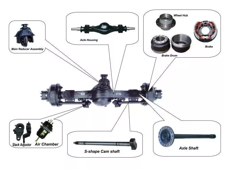
What Is an Axle?
An axle is the central shaft of a vehicle that rotates a wheel or gear. It may be fixed to the wheels or to the vehicle itself, and can rotate with the wheels and gears. It may include bearings and mounting points. If the axle is fixed to the vehicle, it may have a steering or drive shaft attached.
Rear axle
The rear axle is a crucial part of your vehicle. If it fails to function correctly, it can cause major issues when driving at high speeds. This assembly can be a complicated component, and it is crucial that you find a mechanic who knows how to fix it. Rear axles require periodic gear oil replacement and bearing adjustments. The rear axle is the final leg of the drivetrain, transferring rotational power from the driveshaft to the rear wheels. While the design of the rear axle varies between vehicles, all axles are designed to follow similar principles. Rear axles may have a single drive shaft or two. The drive shafts are mounted at either end of the axle. The rear axle ratio is important because it affects how much fuel the truck uses. The lower the ratio, the more fuel-efficient the vehicle is. Higher numbers, like 4:10, are better for towing, but they will decrease fuel economy. When choosing a rear axle ratio, be sure to consider how much weight you’ll be hauling. The rear axle is the most complicated part of the vehicle. It has many components and may not be easily visible. However, a properly functioning rear axle is essential for maximizing safety and performance. If you have a problem, you should contact a professional for a quick and easy fix. Even minor issues can make a significant difference in how your car or truck functions. A professional will ensure that your vehicle’s rear axle will be up to OEM standards.
Semi-floating axle
A semi-floating axle is the next step up from a stub axle. Semi-floating axles have a bearing that supports the shaft, which then floats inside the axle casing. These axles are best suited for midsize trucks. They are also lighter than full-floating axles and can be manufactured at a lower cost. This design is most commonly found on rear-wheel-drive passenger cars and lighter trucks. The semi-floating design also allows for a wider diameter axle shaft, and it can increase axle capacity by increasing the diameter of the axle shaft. It also has a wider offset to accommodate larger tires. It can accommodate any offset, although this is usually only useful in off-road environments. Semi-floating axles are often made with a tapered end. This helps keep the axel from twisting while providing traction. The rear hub of a semi-floating axle is usually connected to the axel via a big, strong nut. This nut also provides friction on the axel shaft. A full-floating axle is common in 3/4-ton and 1/2-ton trucks. It is important to note, however, that almost all factory full-floating rear ends use eight-lug wheels. However, this rule is not strictly enforced and some companies, like Czpt, specialize in semi-floating axles and custom axles.
Drive shaft
A drive shaft is an important part of your vehicle’s drivetrain, which helps to transfer torque from the transmission to the drive wheels. You’ll need to know how it functions in order to properly maintain your car. Fortunately, there are a variety of different parts you can use to upgrade your drive shaft. In order to improve the performance of your vehicle’s drivetrain, you can replace your existing drive shaft with an upgraded one. These are available in various lengths, so that you can find the right length and fit for your vehicle. Some shafts can even be customized to fit the exact length of your axle. Generally, short axle shafts are made of solid steel. The longer ones are made of aluminum or carbon fiber. To ensure a smooth and safe ride, they are dynamically balanced to eliminate vibrations. Some models are fitted with giubo joints and universal joints to absorb shock. You can also add flex discs to improve your suspension and dampen the bucking sensation of a drive shaft. You can tell if your drive shaft needs replacement if you hear a clicking noise while driving. This noise is often audible when the vehicle is turning sharply. You should take your vehicle to a mechanic as soon as you hear this noise, or it could lead to a costly repair. In addition to a clicking noise, your car may also be exhibiting a shuddering or vibrating sensation. If you’re experiencing any of these symptoms, you should take your car in for a checkup by an ASE certified technician. If you ignore these warnings, your car’s drive shaft could separate, causing you a lot of damage. The drive shaft is attached to the axle flange by a drive shaft bolt. This is an important part of the drivetrain because it’s the only point where the drive shaft will connect to the axle. If the bolt is too long, it could be vulnerable to damage if the washers don’t fit tightly. The drive shaft socket yoke can also be easily damaged when you loosen the bolt.
U-joint
When you replace a u-joint on an axle, you need to take a few things into consideration. One of these considerations is the type of grease you’re going to use. Some of these greases are better than others, and you should always check for a quality grease before you install a new one. A good grease can help to reduce the friction and improve the temperature resistance of the part. It’s also important to check the u-joint itself. This is the joint between the axle shaft and the wheel. If it’s not functioning properly, it could cause further problems. You should inspect the u-joint every time you change the oil in your vehicle. You can test its lubrication by pressing on the tire with a pry bar or axle stands. You can also try turning the steering wheel fully to test if the joint is loose. A u-joint failure can leave your car inoperable, which can make driving a risky proposition. If the drive shaft loosens and falls to the ground, you could lose control of your car and risk being stranded. In some severe cases, the front of the driveshaft can even drop to the ground and lift the rear of the car, pushing the car sideways. It’s vital to check u-joints regularly, as failure of the u-joint can cause costly and frustrating car repairs. When you notice a bad universal joint, you should consider getting it replaced immediately. The most common symptom of a bad u-joint is a clunking sound during acceleration and deceleration. You may also hear vibrations when the u-joint becomes worn and you drive the car. If you notice these symptoms, contact a qualified technician to perform a proper diagnosis. editor by czh 2023-02-20
High power high torque 10inch 500kg load 48V 800W 67N.m 20A 120RPM DC digital brushless wheel servo hub motor for AGV car
Product Description
Voltage
48V
Outside diameter
10 inch
Encoder
1571 line Incremental Photoelectric Encoder
Efficiency
≥83%
Number of poles
23 poles
Carrying weight
≤500KG/2 sets
Shaft connection
thread
Brake method
electric brake
Excitation mode
permanent magnet type
Tyre form
with pattern
Matching driver
ZLAC8050
Environment temperature
-20 ~ ;
FAQ
1. Factory or trader? We are factory, and have professional R&D team as introduced in company information.
2. How about the delivery? – Sample: 3-5 days. – Bulk order: 15-30 days.
3. What is your after-sales services? 1. Free maintenance within 12 months guarantee, lifetime consultant. 2. Professional solutions in installation and maintence.
4. Why choose us? 1. Factory Price & 24/7 after-sale services. 2. From mold customization to material processing and welding, from fine components to finished assembly, 72 processes, 24 control points, strict aging, finished product inspection.
Standard Length Splined Shafts
Standard Length Splined Shafts are made from Mild Steel and are perfect for most repair jobs, custom machinery building, and many other applications. All stock splined shafts are 2-3/4 inches in length, and full splines are available in any length, with additional materials and working lengths available upon request and quotation. CZPT Manufacturing Company is proud to offer these standard length shafts.
Disc brake mounting interfaces that are splined
There are 2 common disc brake mounting interfaces, splined and center lock. Disc brakes with splined interfaces are more common. They are usually easier to install. The center lock system requires a tool to remove the locking ring on the disc hub. Six-bolt rotors are easier to install and require only 6 bolts. The center lock system is commonly used with performance road bikes. Post mount disc brakes require a post mount adapter, while flat mount disc brakes do not. Post mount adapters are more common and are used for carbon mountain bikes, while flat mount interfaces are becoming the norm on road and gravel bikes. All disc brake adapters are adjustable for rotor size, though. Road bikes usually use 160mm rotors while mountain bikes use rotors that are 180mm or 200mm.
Disc brake mounting interfaces that are helical splined
A helical splined disc brake mounting interface is designed with a splined connection between the hub and brake disc. This splined connection allows for a relatively large amount of radial and rotational displacement between the disc and hub. A loosely splined interface can cause a rattling noise due to the movement of the disc in relation to the hub. The splines on the brake disc and hub are connected via an air gap. The air gap helps reduce heat conduction from the brake disc to the hub. The present invention addresses problems of noise, heat, and retraction of brake discs at the release of the brake. It also addresses issues with skewing and dragging. If you’re unsure whether this type of mounting interface is right for you, consult your mechanic. Disc brake mounting interfaces that are helix-splined may be used in conjunction with other components of a wheel. They are particularly useful in disc brake mounting interfaces for hub-to-hub assemblies. The spacer elements, which are preferably located circumferentially, provide substantially the same function no matter how the brake disc rotates. Preferably, 3 spacer elements are located around the brake disc. Each of these spacer elements has equal clearance between the splines of the brake disc and the hub. Spacer elements 6 include a helical spring portion 6.1 and extensions in tangential directions that terminate in hooks 6.4. These hooks abut against the brake disc 1 in both directions. The helical spring portion 5.1 and 6.1 have stiffness enough to absorb radial impacts. The spacer elements are arranged around the circumference of the intermeshing zone. A helical splined disc mount includes a stabilizing element formed as a helical spring. The helical spring extends to the disc’s splines and teeth. The ends of the extension extend in opposite directions, while brackets at each end engage with the disc’s splines and teeth. This stabilizing element is positioned axially over the disc’s width. Helical splined disc brake mounting interfaces are popular in bicycles and road bicycles. They’re a reliable, durable way to mount your brakes. Splines are widely used in aerospace, and have a higher fatigue life and reliability. The interfaces between the splined disc brake and BB spindle are made from aluminum and acetate. As the splined hub mounts the disc in a helical fashion, the spring wire and disc 2 will be positioned in close contact. As the spring wire contacts the disc, it creates friction forces that are evenly distributed throughout the disc. This allows for a wide range of axial motion. Disc brake mounting interfaces that are helical splined have higher strength and stiffness than their counterparts. Disc brake mounting interfaces that are helically splined can have a wide range of splined surfaces. The splined surfaces are the most common type of disc brake mounting interfaces. They are typically made of stainless steel or aluminum and can be used for a variety of applications. However, a splined disc mount will not support a disc with an oversized brake caliper.
Most use in Amusement equipment, Stroller, Bumper car, Electric scooter, Folding generation drive, scooter, Drift car, Small train and So on.
Specifications:
Motor
6″brushless geared wheel motor
Voltage
24V
Rated Power
180W
Wheelchair speed
5km/h
Rated speed
150rpm
Rated Torque
12Nm
Diameter
155
Weight
3.1kg
Loading
80~300kg
Brake
Electronic brake(EABS)/Disc brake
Reduction ratio
1:5
Waterproof Rating
IP54
Tire
Solid tire
The Different Types of Splines in a Splined Shaft
A splined shaft is a machine component with internal and external splines. The splines are formed in 4 different ways: Involute, Parallel, Serrated, and Ball. You can learn more about each type of spline in this article. When choosing a splined shaft, be sure to choose the right 1 for your application. Read on to learn about the different types of splines and how they affect the shaft’s performance.
Involute splines
Involute splines in a splined shaft are used to secure and extend mechanical assemblies. They are smooth, inwardly curving grooves that resist separation during operation. A shaft with involute splines is often longer than the shaft itself. This feature allows for more axial movement. This is beneficial for many applications, especially in a gearbox. The involute spline is a shaped spline, similar to a parallel spline. It is angled and consists of teeth that create a spiral pattern that enables linear and rotatory motion. It is distinguished from other splines by the serrations on its flanks. It also has a flat top. It is a good option for couplers and other applications where angular movement is necessary. Involute splines are also called involute teeth because of their shape. They are flat on the top and curved on the sides. These teeth can be either internal or external. As a result, involute splines provide greater surface contact, which helps reduce stress and fatigue. Regardless of the shape, involute splines are generally easy to machine and fit. Involute splines are a type of splines that are used in splined shafts. These splines have different names, depending on their diameters. An example set of designations is for a 32-tooth male spline, a 2,500-tooth module, and a 30 degree pressure angle. An example of a female spline, a fillet root spline, is used to describe the diameter of the splined shaft. The effective tooth thickness of splines is dependent on the number of keyways and the type of spline. Involute splines in splined shafts should be designed to engage 25 to 50 percent of the spline teeth during the coupling. Involute splines should be able to withstand the load without cracking.
Parallel splines
Parallel splines are formed on a splined shaft by putting 1 or more teeth into another. The male spline is positioned at the center of the female spline. The teeth of the male spline are also parallel to the shaft axis, but a common misalignment causes the splines to roll and tilt. This is common in many industrial applications, and there are a number of ways to improve the performance of splines. Typically, parallel splines are used to reduce friction in a rotating part. The splines on a splined shaft are narrower on the end face than the interior, which makes them more prone to wear. This type of spline is used in a variety of industries, such as machinery, and it also allows for greater efficiency when transmitting torque. Involute splines on a splined shaft are the most common. They have equally spaced teeth, and are therefore less likely to crack due to fatigue. They also tend to be easy to cut and fit. However, they are not the best type of spline. It is important to understand the difference between parallel and involute splines before deciding on which spline to use. The difference between splined and involute splines is the size of the grooves. Involute splines are generally larger than parallel splines. These types of splines provide more torque to the gear teeth and reduce stress during operation. They are also more durable and have a longer life span. And because they are used on farm machinery, they are essential in this type of application.
Serrated splines
A Serrated Splined Shaft has several advantages. This type of shaft is highly adjustable. Its large number of teeth allows large torques, and its shorter tooth width allows for greater adjustment. These features make this type of shaft an ideal choice for applications where accuracy is critical. Listed below are some of the benefits of this type of shaft. These benefits are just a few of the advantages. Learn more about this type of shaft. The process of hobbing is inexpensive and highly accurate. It is useful for external spline shafts, but is not suitable for internal splines. This type of process forms synchronized shapes on the shaft, reducing the manufacturing cycle and stabilizing the relative phase between spline and thread. It uses a grinding wheel to shape the shaft. CZPT Manufacturing has a large inventory of Serrated Splined Shafts. The teeth of a Serrated Splined Shaft are designed to engage with the hub over the entire circumference of the shaft. The teeth of the shaft are spaced uniformly around the spline, creating a multiple-tooth point of contact over the entire length of the shaft. The results of these analyses are usually satisfactory. But there are some limitations. To begin with, the splines of the Serrated Splined Shaft should be chosen carefully. If the application requires large-scale analysis, it may be necessary to modify the design. The splines of the Serrated Splined Shaft are also used for other purposes. They can be used to transmit torque to another device. They also act as an anti-rotational device and function as a linear guide. Both the design and the type of splines determine the function of the Splined Shaft. In the automobile industry, they are used in vehicles, aerospace, earth-moving machinery, and many other industries.
Ball splines
The invention relates to a ball-spinned shaft. The shaft comprises a plurality of balls that are arranged in a series and are operatively coupled to a load path section. The balls are capable of rolling endlessly along the path. This invention also relates to a ball bearing. Here, a ball bearing is 1 of the many types of gears. The following discussion describes the features of a ball bearing. A ball-splined shaft assembly comprises a shaft with at least 1 ball-spline groove and a plurality of circumferential step grooves. The shaft is held in a first holding means that extends longitudinally and is rotatably held by a second holding means. Both the shaft and the first holding means are driven relative to 1 another by a first driving means. It is possible to manufacture a ball-splined shaft in a variety of ways. A ball-splined shaft features a nut with recirculating balls. The ball-splined nut rides in these grooves to provide linear motion while preventing rotation. A splined shaft with a nut that has recirculating balls can also provide rotary motion. A ball splined shaft also has higher load capacities than a ball bushing. For these reasons, ball splines are an excellent choice for many applications. In this invention, a pair of ball-spinned shafts are housed in a box under a carrier device 40. Each of the 2 shafts extends along a longitudinal line of arm 50. One end of each shaft is supported rotatably by a slide block 56. The slide block also has a support arm 58 that supports the center arm 50 in a cantilever fashion.
Sector no-go gage
A no-go gauge is a tool that checks the splined shaft for oversize. It is an effective way to determine the oversize condition of a splined shaft without removing the shaft. It measures external splines and serrations. The no-go gage is available in sizes ranging from 19mm to 130mm with a 25mm profile length. The sector no-go gage has 2 groups of diametrally opposed teeth. The space between them is manufactured to a maximum space width and the tooth thickness must be within a predetermined tolerance. This gage would be out of tolerance if the splines were measured with a pin. The dimensions of this splined shaft can be found in the respective ANSI or DIN standards. The go-no-go gage is useful for final inspection of thread pitch diameter. It is also useful for splined shafts and threaded nuts. The thread of a screw must match the contour of the go-no-go gage head to avoid a no-go condition. There is no substitute for a quality machine. It is an essential tool for any splined shaft and fastener manufacturer. The NO-GO gage can detect changes in tooth thickness. It can be calibrated under ISO17025 standards and has many advantages over a non-go gage. It also gives a visual reference of the thickness of a splined shaft. When the teeth match, the shaft is considered ready for installation. It is a critical process. In some cases, it is impossible to determine the precise length of the shaft spline. The 45-degree pressure angle is most commonly used for axles and torque-delivering members. This pressure angle is the most economical in terms of tool life, but the splines will not roll neatly like a 30 degree angle. The 45-degree spline is more likely to fall off larger than the other two. Oftentimes, it will also have a crowned look. The 37.5 degree pressure angle is a compromise between the other 2 pressure angles. It is often used when the splined shaft material is harder than usual.
CE certification 10inch 48V 800W 500kg load 67N.m 20A 120RPM brushless DC wheel hub servo motor for moving robot
Product Description
Voltage
48V
Outside diameter
10 inch
Encoder
1571 line Incremental Photoelectric Encoder
Efficiency
≥83%
Number of poles
23 poles
Carrying weight
≤500KG/2 sets
Shaft connection
thread
Brake method
electric brake
Excitation mode
permanent magnet type
Tyre form
with pattern
Matching driver
ZLAC8050
Environment temperature
-20 ~ ;
FAQ
1. Factory or trader? We are factory, and have professional R&D team as introduced in company information.
2. How about the delivery? – Sample: 3-5 days. – Bulk order: 15-30 days.
3. What is your after-sales services? 1. Free maintenance within 12 months guarantee, lifetime consultant. 2. Professional solutions in installation and maintence.
4. Why choose us? 1. Factory Price & 24/7 after-sale services. 2. From mold customization to material processing and welding, from fine components to finished assembly, 72 processes, 24 control points, strict aging, finished product inspection.
Screw Shaft Types
If you’re looking for a screw shaft, but aren’t sure which type to buy, you’re in luck. In this article, we’ll talk about the different types, including Threaded shank, Round head, and Machined. Once you’ve read it, you’ll know which type to buy. Then, you can decide whether you want a ball screw nut or a threaded shank.
Machined screw shafts
Besides the standard stainless steel shaft, manufacturers also provide a variety of other materials, such as titanium, bronze, and brass. In addition to stainless steel, manufacturers also provide a variety of top-coating options, including zinc, brass, and chromium. Aluminum screws are not particularly durable and are easily affected by weather. Most screw shafts feature self-locking mechanisms. They are especially useful in C-clamps, vises, and screw-top container lids. For applications where accuracy is vital, a ball screw shaft needs to be annealed. A heat treatment can be performed on the ball screw shaft to ensure that both ends are heated evenly. In this process, the shaft will be more durable, while maintaining its high-precision properties. These screw shafts are a key component in computer-controlled motion-control systems, wire bonding, and other industries that require high-precision and high-quality performance. Depending on the material used, screw shafts can be made of stainless steel or titanium. High-precision CNC machines and lathes are typically used to manufacture screw shafts. Various shapes and sizes are available, each with a specific application. Whether you need a small or large screw, you can find 1 to fit your needs. And since each size requires a different material, your choice of material is important as well. In general, the materials used for machining screw shafts are steel, stainless steel, titanium, brass, bronze, and aluminum. Metals that resist corrosion are also commonly used. Other materials for screw shafts are Teflon, nylon, and nylon. You can also find threaded screw shafts in materials such as porcelain, glass, and ceramic. If you want to use your screws in a unique material, consider purchasing a customized one.
Ball screw nuts
If you have a screw shaft, the last thing you want to worry about is the ball nut slipping off. To prevent this, you can place a temporary stop in the shaft’s grooves to ensure that the ball nut does not slide off. When you remove the stop, you can then install the ball screw nut. But, before you can install the ball screw nut, you have to make sure that you have a good grip on the shaft. When selecting ball screw nuts, it’s important to consider how much preload you need to apply to avoid excessive backlash. Preloading eliminates this problem by making the ball nut compact. It also prevents backlash, which is lost motion caused by clearance between the ball and nut. Backlash disrupts repeatability and accuracy. This is where spacer preloading comes in. You can insert a spacer between the 2 ball nuts to transmit the force to the nut. However, you should keep in mind that this method reduces the load capacity of the ball screw. The critical speed of a screw is the maximum rotating speed before it whips. This critical speed is influenced by several factors, including the diameter of the screw shaft, the number of support elements, and the material. By adjusting these factors, you can reduce the number of components used and the amount of time it takes to assemble the screw shaft. In addition, you can also reduce the number of components and avoid stacking tolerances. However, the critical speed of plastic nuts is limited due to sliding friction. The ball screw nut has several characteristics that make it unique. Its most prominent feature is the presence of ball bearings. These balls help reduce friction between the screw nut and the shaft. Without ball bearings, the friction would be too high to function properly. Another important characteristic is the groove profile of the nut and ball. These 2 features ensure that the ball and the nut meet at 2 points. You’ll be amazed by the results of the work of these ball screw nuts.
Threaded shank
Wood screws are usually not fully threaded because the shank has an unthreaded portion at the top. This shoulder part forces the screw to compress 2 pieces of wood, which prevents the screw from overheating and compromising the materials strength. As the screw is threaded partially up, it is not as difficult to remove as a fully threaded screw. However, it is important to note that a wood screw will not hold as tightly as 1 with a fully threaded shank. In addition to being universal, screw threads can be of different sizes. For example, a M8 screw has a thread pitch of 1.25 mm. To avoid confusion, screw thread pitches are commonly given with a multiplication sign. For example, M8x1 means that the screw is 8 mm in diameter but has a thread pitch of 1 mm per 360-degree rotation. Those who are not familiar with these dimensions may find it confusing. The OD of the threaded portion of a bolt is generally smaller than the OD of the nut. If the shank is too deep for the nut to fit, the threads may bottom out. This is why it’s important to use a thread-cutting bit with a small thread diameter. You can use a micrometer or caliper to measure the thread diameter. This tool will also allow you to easily identify which screw size fits where and how well. The metric system is the most widely used. Fasteners with DIN numbers are generally metric in size. This makes them very useful for industrial settings. You can find metric-sized screws anywhere, as long as you buy them from a reputable manufacturer. These fasteners also come with a dog point, which is used for safety wire. If the screw needs to be replaced, the shank can be drilled with a hole for a safety wire or for a dog-point.
Round head
A round head screw is the most common type used for machine screws. Other common types include truss head, flat head, and hexed head. Each has a different profile and are used for different purposes. A round head screw is typically wider than a flat or a hexed head, and has a slightly rounded surface. These screws are useful for projects involving sheet metal or sheet-metal parts. Round heads are usually slightly wider than a hex head screw, and they may also be used as a substitute for washers in certain applications. However, truss heads are not necessary for every project. A wood screw has a smooth shank that protrudes above the surface of the material it is attaching. A metal screw has a threaded shaft that is fully threaded from head to point, and a fully threaded shaft provides more bite. Two common head styles are round head and pan head. If the task requires the screw to be flush or countersunk, the round head will be the best choice. Another type is the Reed & Prince screw drive. These are similar to Phillips screws but have a 75-degree V shape. They are commonly used in marine hardware and are also known as BNAE NFL22-070. This type is also used for steel plate hangers. In addition to round head and pan head screws, there are a variety of other screw types. You can even get a head with a slotted head if you know where to look. Screw diameters are specified according to the ISO 261 or ISO 262 standards. An M8 screw has a diameter of 8.25 mm. The M8 screw has a pitch of 1.25 mm, which is equivalent to 1 mm per 360 degrees. There are several other standard screw sizes and thread diameters available. You can find them all by consulting the relevant standards. But remember, the metric system is the most popular.
Self-locking mechanism
A self-locking mechanism for a screw shaft is a device that secures the screw to its supporting member in a failure position. The locking mechanism provides a positive connection between the screw shaft and the control surface during normal operation, and locks the screw to its supporting member when the screw fails. Previous attempts to solve this problem have typically used secondary nuts with free play on the screw, which were intentionally designed to jam when loaded. However, such a device can be unreliable, which is why the present invention offers a more robust and reliable locking mechanism. The self-locking function of a screw depends on several factors, including its pitch angle and the coefficient of friction of the threads. The angle of friction must be less than the tangent of the material pairing to prevent untightening of the screw. Screws with self-locking mechanisms have an efficiency e lower than 50%, which is less than half. Self-locking screws also have the benefit of being less efficient than a standard screw. Unlike a normal screw, a self-locking screw can be turned in either direction. The nut 22 rotates with the screw shaft, and the member 23 is translated in an axial direction. Regardless of the direction of the rotation of the screw, this axial translation will result in the opposite moment to that input moment. While screw self-locking mechanisms are typically less expensive, they are more reliable and durable. Another important feature of self-locking screws is that they are not susceptible to independent loosening. The screw cannot rotate without a certain amount of torque. In addition, a self-locking screw shaft must have a small wedge with a smaller half-angle than the arctangent of the static friction. This means that the torque applied by the driver must be greater than the torque needed to overcome the friction.
EThrone Lightweight Portable Brushless Folding Electric Wheelchair With TUV CE Approved, safe, secure, reliable!
E-throne Wheelchair is design with extremely compact size and strongest aluminum frame, very smooth motor drive control, safe lithium battery pack, very conveient to take on an train, bus, air plane, with it`s durable 8″10″12″ rear motor wheels. It can easily handle all of the outdoor areas you wish to go.
Top Quality Workmanship, Comfortable Riding Experience Guaranteed! Super Light, Quickest Folding/Unfolding, Inclineable Back, Sturdy Aluminium Frame, 50% Battery Saving, 28km Travel Range, 10 times Longer Motor Life, Maintenance Free…
Special Features of this foldable power wheelchair: 1. Light weight <30 Kg 2. Quickest Foldable – easy folding/unfolding in a second 3. Longer travel HangZhouage: Over 28 Km (18 HangZhous) 4. Back rest tilting – 5 inclinable angles 5. Well designed frame for comfortable riding 6. Support heavy load: Max 150 Kg 7. Breakthrough brushless wheelchair drive technologies: High efficiency brushless hub motor Brushless joystick controller 50% battery saving 10 times longer working life 8. Best quality LiFePO4 battery: 24V15AH (4.6 Kg) 1000 charging cycles Safe, light, reliable Pollution free 9. Self upgradeable wheel sizes – 8″/10″/12″ 10. Longer warranty period
The specifications of our e-Throne electric folding wheelchairs(8”, 10”, 12” available):
Customer’s Experience about this innovative folding electric wheelchair “I just recently purchased a ET-08F22 wheelchair and with the batteries arriving Tuesday I have been using it for the last 2 days. I have to congratulate Golden Motors on the design of this chair. It is brilliant in the way it folds so easily, so small and light, perfect for travel and strong enough for many everyday uses. You can say that I am a very pleased customer. ” — Greg Burge, USA
I would like to thank Golden Motor for giving me back the opportunity to travel with ease. Before purchasing my Golden Motor e-Throne chair, Traveling was a true nightmare. It’s extremely hard to travel with a Power Chair that alone weighs 420 LB. Most Planes as well as Transportation are not equipped or are not available in different countries. It’s extremely hard to find vehicles that are equipped with Lifts to be CZPT to transport. That’s were Golden Motor comes into Place. It’s the Lightest Portable Power Wheelchair I’ve ever came across. Weighs only 50 pounds and it folds in to just 1 single unit that is the size of a luggage. Because of this I have been CZPT to now travel with ease. Fits in any vehicle trunk or front seat. Great for when you travel by Bus, Taxi, rental car or even a Friends personal car. Most of the time because of its size it can fit on the inside closet of the Airplanes. My family and I now can really enjoy traveling. See some of the places we have travel to such as Spain, Paris, and Onboard The CZPT of the Seas. Give yourself the opportunity to get out there and enjoy life. — CZPT T., Orlando, FL
I had the opportunity over the last 2 months of travel nearly 200 km with the e-Throne wheelchair. This is a collection of my impressions which are generally satisfactory, if not excellent. Tens of kilometers on very poorly paved paths allowed me to appreciate its handling and its solidity. Besides the good look, noticed by everyone and which is less disabled, the weight and volume of this chair makes it extremely convenient for travel, almost essential. It was easy to carry with me the chair that is light when there was a barrier. The ability to store it in the trunk of any vehicle used to go everywhere. I actually had to sell 5 or 6 chairs around the world because many people wanted to photograph the chair and I gave them your address. For a month, I have with my wife who loves this chair for its light weight and easy folding traveled the following countries and cities: Finland, Paris, Italy, Croatia, Montenegro, Ibiza, Venice, London and France. Everywhere, I realized for you pictures to show the chair in these famous parts of the world. — Pierre H., New Caledonia
I just want to tell you how I love this Chair! I am 5’9″ and it is such a comfortable ride! I have a 3 wheeled scooter (which comes apart in 4 pieces for travel so I would never take it anywhere) which is cumbersome to try to travel with and the ride is so rough so when I received this chair I was so impressed with the ride! We took it to the Casino here in Vegas which has a movie theater and it maneuvered so well in and around the casino as well as the elevator and handicap restrooms and also the Mall shopping center. While the weight of the chair is still a bit much for me with my Multiple Sclerosis my husband is CZPT to fold it and fit in the trunk. I feel as though I have my freedom back now that my husband does not have to push me anymore! ! — Melani F., Las Vegas, NV
What is a drive shaft?
If you notice a clicking noise while driving, it is most likely the driveshaft. An experienced auto mechanic will be able to tell you if the noise is coming from both sides or from 1 side. If it only happens on 1 side, you should check it. If you notice noise on both sides, you should contact a mechanic. In either case, a replacement driveshaft should be easy to find.
The drive shaft is a mechanical part
A driveshaft is a mechanical device that transmits rotation and torque from the engine to the wheels of the vehicle. This component is essential to the operation of any driveline, as the mechanical power from the engine is transmitted to the PTO (power take-off) shaft, which hydraulically transmits that power to connected equipment. Different drive shafts contain different combinations of joints to compensate for changes in shaft length and angle. Some types of drive shafts include connecting shafts, internal constant velocity joints, and external fixed joints. They also contain anti-lock system rings and torsional dampers to prevent overloading the axle or causing the wheels to lock. Although driveshafts are relatively light, they need to handle a lot of torque. Torque applied to the drive shaft produces torsional and shear stresses. Because they have to withstand torque, these shafts are designed to be lightweight and have little inertia or weight. Therefore, they usually have a joint, coupling or rod between the 2 parts. Components can also be bent to accommodate changes in the distance between them. The drive shaft can be made from a variety of materials. The most common material for these components is steel, although alloy steels are often used for high-strength applications. Alloy steel, chromium or vanadium are other materials that can be used. The type of material used depends on the application and size of the component. In many cases, metal driveshafts are the most durable and cheapest option. Plastic shafts are used for light duty applications and have different torque levels than metal shafts.
It transfers power from the engine to the wheels
A car’s powertrain consists of an electric motor, transmission, and differential. Each section performs a specific job. In a rear-wheel drive vehicle, the power generated by the engine is transmitted to the rear tires. This arrangement improves braking and handling. The differential controls how much power each wheel receives. The torque of the engine is transferred to the wheels according to its speed. The transmission transfers power from the engine to the wheels. It is also called “transgender”. Its job is to ensure power is delivered to the wheels. Electric cars cannot drive themselves and require a gearbox to drive forward. It also controls how much power reaches the wheels at any given moment. The transmission is the last part of the power transmission chain. Despite its many names, the transmission is the most complex component of a car’s powertrain. The driveshaft is a long steel tube that transmits mechanical power from the transmission to the wheels. Cardan joints connect to the drive shaft and provide flexible pivot points. The differential assembly is mounted on the drive shaft, allowing the wheels to turn at different speeds. The differential allows the wheels to turn at different speeds and is very important when cornering. Axles are also important to the performance of the car.
It has a rubber boot that protects it from dust and moisture
To keep this boot in good condition, you should clean it with cold water and a rag. Never place it in the dryer or in direct sunlight. Heat can deteriorate the rubber and cause it to shrink or crack. To prolong the life of your rubber boots, apply rubber conditioner to them regularly. Indigenous peoples in the Amazon region collect latex sap from the bark of rubber trees. Then they put their feet on the fire to solidify the sap.
it has a U-shaped connector
The drive shaft has a U-joint that transfers rotational energy from the engine to the axle. Defective gimbal joints can cause vibrations when the vehicle is in motion. This vibration is often mistaken for a wheel balance problem. Wheel balance problems can cause the vehicle to vibrate while driving, while a U-joint failure can cause the vehicle to vibrate when decelerating and accelerating, and stop when the vehicle is stopped. The drive shaft is connected to the transmission and differential using a U-joint. It allows for small changes in position between the 2 components. This prevents the differential and transmission from remaining perfectly aligned. The U-joint also allows the drive shaft to be connected unconstrained, allowing the vehicle to move. Its main purpose is to transmit electricity. Of all types of elastic couplings, U-joints are the oldest. Your vehicle’s U-joints should be inspected at least twice a year, and the joints should be greased. When checking the U-joint, you should hear a dull sound when changing gears. A clicking sound indicates insufficient grease in the bearing. If you hear or feel vibrations when shifting gears, you may need to service the bearings to prolong their life.
it has a slide-in tube
The telescopic design is a modern alternative to traditional driveshaft designs. This innovative design is based on an unconventional design philosophy that combines advances in material science and manufacturing processes. Therefore, they are more efficient and lighter than conventional designs. Slide-in tubes are a simple and efficient design solution for any vehicle application. Here are some of its benefits. Read on to learn why this type of shaft is ideal for many applications. The telescopic drive shaft is an important part of the traditional automobile transmission system. These driveshafts allow linear motion of the 2 components, transmitting torque and rotation throughout the vehicle’s driveline. They also absorb energy if the vehicle collides. Often referred to as foldable driveshafts, their popularity is directly dependent on the evolution of the automotive industry.
It uses a bearing press to replace worn or damaged U-joints
A bearing press is a device that uses a rotary press mechanism to install or remove worn or damaged U-joints from a drive shaft. With this tool, you can replace worn or damaged U-joints in your car with relative ease. The first step involves placing the drive shaft in the vise. Then, use the 11/16″ socket to press the other cup in far enough to install the clips. If the cups don’t fit, you can use a bearing press to remove them and repeat the process. After removing the U-joint, use a grease nipple Make sure the new grease nipple is installed correctly. Worn or damaged U-joints are a major source of driveshaft failure. If 1 of them were damaged or damaged, the entire driveshaft could dislocate and the car would lose power. Unless you have a professional mechanic doing the repairs, you will have to replace the entire driveshaft. Fortunately, there are many ways to do this yourself. If any of these warning signs appear on your vehicle, you should consider replacing the damaged or worn U-joint. Common symptoms of damaged U-joints include rattling or periodic squeaking when moving, rattling when shifting, wobbling when turning, or rusted oil seals. If you notice any of these symptoms, take your vehicle to a qualified mechanic for a full inspection. Neglecting to replace a worn or damaged u-joint on the driveshaft can result in expensive and dangerous repairs and can cause significant damage to your vehicle.
10mm 3V High Precision CCTV Camera Geared Motor With Gearbox
Product Parameters
Model: ZWBMD571571-168
Rated Voltage: 3.0V
No Load Speed: 98 rpm
No Load Current: 80mA
Rated Load Speed: 86 rpm
Rated Load Current: 220mA
Rated Load Torque: 106 gf.cm
Rated Torque of Gear Box: 2,000 gf.cm
Instant Torque of Gear Box: 6,000 gf.cm
Overall Length L: 34 mm
Gear Box Length L1: 19 mm
Model
Application Parameters
Rated Torque of Gear Box
Instant Torque of Gear Box
Gear Ratio
Gear Box Length L1
Rated
At No Load
At Rated Load
Overall Length L
Voltage
Speed
Current
Speed
Current
Torque
VDC
rpm
mA
rpm
mA
gf.cm
mN.m
mm
gf.cm
gf.cm
mm
ZWBMD571571-46
3.0
375
80
315
215
39
3.8
30.9
2000
6000
46
15.9
ZWBMD571571-69
3.0
250
80
210
215
58
5.7
2000
6000
69
ZWBMD571571-102
3.0
169
80
142
215
86
8.4
2000
6000
102
ZWBMD571571-151
3.0
114
80
96
215
127
12.5
2000
6000
151
ZWBMD571571-168
3.0
98
80
86
220
106
10.4
34
2000
6000
168
19
ZWBMD571571-249
3.0
66
80
58
220
158
15
2000
6000
249
ZWBMD571571-368
3.0
45
80
39
220
233
23
2000
6000
368
ZWBMD571571-546
3.0
30
80
27
220
346
34
2000
6000
546
ZWBMD571571-809
3.0
20
80
18
220
512
50
2000
6000
809
above specifications just for reference and customizable according to requirements.
Please let us know your requirements and we will provide you with micro transmission solutions.
Detailed Photos
Application
Smart wearable devices
watch,VR,AR,XR and etc.
Household application
kitchen appliances, sewing machines, corn popper, vacuum cleaner, garden tool, sanitary ware, window curtain, intelligent closestool, sweeping robot, power seat, standing desk, electric sofa, TV, computer, treadmill, spyhole, cooker hood, electric drawer, electric mosquito net, intelligent cupboard, intelligent wardrobe, automatic soap dispenser, UV baby bottle sterilizer, lifting hot pot cookware, dishwasher, washing machine, food breaking machine, dryer, air conditioning, dustbin, coffee machine, whisk,smart lock,bread maker,Window cleaning robot and etc.
communication equipment
5G base station,video conference,mobile phone and etc.
Office automation equipments
scanners, printers, multifunction machines copy machines, fax (FAX paper cutter), computer peripheral, bank machine, screen, lifting socket, display,notebook PC and etc.
Automotive products
conditioning damper actuator, car DVD,door lock actuator, retractable rearview mirror, meters, optic axis control device, head light beam level adjuster, car water pump, car antenna, lumbar support, EPB, car tail gate electric putter, HUD, head-up display, vehicle sunroof, EPS, AGS, car window, head restraint, E-booster, car seat, vehicle charging station and etc.
Toys and models
radio control model, automatic cruise control, ride-on toy, educational robot, programming robot, medical robot, automatic feeder, intelligent building blocks, escort robot and etc.
Medical equipments
blood pressure meter, breath machine, medical cleaning pump, medical bed, blood pressure monitors, medical ventilator, surgical staplers, infusion pump, dental instrument, self-clotting cutter, wound cleaning pump for orthopedic surgery,electronic cigarette, eyebrow pencil,fascia gun, , surgical robot,laboratory automation and etc.
Industrials
flow control valves, seismic testing,automatic reclosing,Agricultural unmanned aerial vehicle,automatic feeder ,intelligent express cabinet and etc.
Electric power tools
electric drill, screwdriver,garden tool and etc.
Precision instruments
optics instruments,automatic vending machine, wire-stripping machine and etc.
camera, mobile phone,digital camera, automatic retracting device,camcorder, kinescope DVD,headphone stereo, cassette tape recorder, bluetooth earbud charging case, turntable, tablet,UAV(unmanned aerial vehicle),surveillance camera,PTZ camera, rotating smart speaker and etc.
robots
educational robot, programming robot, medical robot, escort robot and etc.
Company Profile
HangZhou CZPT Machinery & Electronics Co., Ltd was established in 2001,We provide the total drive solution for customers from design, tooling fabrication, components manufacturing and assembly.
Workshop
Testing Equipment
1) Competitive Advantages
1) Competitive Advantages 19+year experience in manufacturing motor gearbox We provide technical support from r&d, prototype, testing, assembly and serial production , ODM &OEM Competitive Price Product Performance: Low noise, High efficiency, Long lifespan Prompt Delivery: 15 working days after payment Small Orders Accepted
2) Main Products
Precision reduction gearbox and its diameter:3.4mm-38mm,voltage:1.5-24V,power: 0.01-40W,output speed:5-2000rpm and output torque:1.0 gf.cm -50kgf.cm,
Customized worm and gear transmission machinery;
Precise electromechanical motion module;
Precise component and assembly of plastic and metal powder injection.
Our Services
ODM & OEM
Gearbox design and development
Related technology support
Micro drive gearbox custom solution
Packaging & Shipping
1) Packing Details
packed in nylon firstly, then carton, and then reinforced with wooden case for outer packing. Or according to client’s requirement.
2) Shipping Details
samples will be shipped within 10 days; batch order leading time according to the actual situation.
Certifications
Certifications
We Have passed to hold ISO9001:2015(CN11/3571),ISO14001:2004(U006616E0153R3M), ISO13485:2016(CN18/42018) and IATF16949:2016(CN11/3571.01).
and more…
FAQ
FAQ
1. Can you make the gearbox with custom specifications? YES. We have design and development team, also a great term of engineers, each of them have many work years experience.
2.Do you provide the samples? YES. Our company can provide the samples to you, and the delivery time is about 5-15days according to the specification of gearbox you need.
3.What is your MOQ? Our MOQ is 2000pcs. But at the beginning of our business, we accept small order.
4. Do you have the item in stock? I am sorry we donot have the item in stock, All products are made with orders.
5. Do you provide technology support? YES. Our company have design and development team, we can provide technology support if you need.
6.How to ship to us? We will ship the goods to you according to the DHL or UPS or FEDEX etc account you provide.
7.How to pay the money? We accept T/T in advance. Also we have different bank account for receiving money, like US dollors or RMB etc.
8. How can I know the product is suitable for me? Frist, you need to provide us the more details information about the product. We will recommend the item to you according to your requirement of specification. After you confirm, we will prepare the samples to you. also we will offer some good advances according to your product use.
9. Can I come to your company to visit? YES, you can come to our company to visit at anytime, and welcome to visit our company.
10. How do contact us ? Please send an inquiry
What is a drive shaft?
If you notice a clicking noise while driving, it is most likely the driveshaft. An experienced auto mechanic will be able to tell you if the noise is coming from both sides or from 1 side. If it only happens on 1 side, you should check it. If you notice noise on both sides, you should contact a mechanic. In either case, a replacement driveshaft should be easy to find.
The drive shaft is a mechanical part
A driveshaft is a mechanical device that transmits rotation and torque from the engine to the wheels of the vehicle. This component is essential to the operation of any driveline, as the mechanical power from the engine is transmitted to the PTO (power take-off) shaft, which hydraulically transmits that power to connected equipment. Different drive shafts contain different combinations of joints to compensate for changes in shaft length and angle. Some types of drive shafts include connecting shafts, internal constant velocity joints, and external fixed joints. They also contain anti-lock system rings and torsional dampers to prevent overloading the axle or causing the wheels to lock. Although driveshafts are relatively light, they need to handle a lot of torque. Torque applied to the drive shaft produces torsional and shear stresses. Because they have to withstand torque, these shafts are designed to be lightweight and have little inertia or weight. Therefore, they usually have a joint, coupling or rod between the 2 parts. Components can also be bent to accommodate changes in the distance between them. The drive shaft can be made from a variety of materials. The most common material for these components is steel, although alloy steels are often used for high-strength applications. Alloy steel, chromium or vanadium are other materials that can be used. The type of material used depends on the application and size of the component. In many cases, metal driveshafts are the most durable and cheapest option. Plastic shafts are used for light duty applications and have different torque levels than metal shafts.
It transfers power from the engine to the wheels
A car’s powertrain consists of an electric motor, transmission, and differential. Each section performs a specific job. In a rear-wheel drive vehicle, the power generated by the engine is transmitted to the rear tires. This arrangement improves braking and handling. The differential controls how much power each wheel receives. The torque of the engine is transferred to the wheels according to its speed. The transmission transfers power from the engine to the wheels. It is also called “transgender”. Its job is to ensure power is delivered to the wheels. Electric cars cannot drive themselves and require a gearbox to drive forward. It also controls how much power reaches the wheels at any given moment. The transmission is the last part of the power transmission chain. Despite its many names, the transmission is the most complex component of a car’s powertrain. The driveshaft is a long steel tube that transmits mechanical power from the transmission to the wheels. Cardan joints connect to the drive shaft and provide flexible pivot points. The differential assembly is mounted on the drive shaft, allowing the wheels to turn at different speeds. The differential allows the wheels to turn at different speeds and is very important when cornering. Axles are also important to the performance of the car.
It has a rubber boot that protects it from dust and moisture
To keep this boot in good condition, you should clean it with cold water and a rag. Never place it in the dryer or in direct sunlight. Heat can deteriorate the rubber and cause it to shrink or crack. To prolong the life of your rubber boots, apply rubber conditioner to them regularly. Indigenous peoples in the Amazon region collect latex sap from the bark of rubber trees. Then they put their feet on the fire to solidify the sap.
it has a U-shaped connector
The drive shaft has a U-joint that transfers rotational energy from the engine to the axle. Defective gimbal joints can cause vibrations when the vehicle is in motion. This vibration is often mistaken for a wheel balance problem. Wheel balance problems can cause the vehicle to vibrate while driving, while a U-joint failure can cause the vehicle to vibrate when decelerating and accelerating, and stop when the vehicle is stopped. The drive shaft is connected to the transmission and differential using a U-joint. It allows for small changes in position between the 2 components. This prevents the differential and transmission from remaining perfectly aligned. The U-joint also allows the drive shaft to be connected unconstrained, allowing the vehicle to move. Its main purpose is to transmit electricity. Of all types of elastic couplings, U-joints are the oldest. Your vehicle’s U-joints should be inspected at least twice a year, and the joints should be greased. When checking the U-joint, you should hear a dull sound when changing gears. A clicking sound indicates insufficient grease in the bearing. If you hear or feel vibrations when shifting gears, you may need to service the bearings to prolong their life.
it has a slide-in tube
The telescopic design is a modern alternative to traditional driveshaft designs. This innovative design is based on an unconventional design philosophy that combines advances in material science and manufacturing processes. Therefore, they are more efficient and lighter than conventional designs. Slide-in tubes are a simple and efficient design solution for any vehicle application. Here are some of its benefits. Read on to learn why this type of shaft is ideal for many applications. The telescopic drive shaft is an important part of the traditional automobile transmission system. These driveshafts allow linear motion of the 2 components, transmitting torque and rotation throughout the vehicle’s driveline. They also absorb energy if the vehicle collides. Often referred to as foldable driveshafts, their popularity is directly dependent on the evolution of the automotive industry.
It uses a bearing press to replace worn or damaged U-joints
A bearing press is a device that uses a rotary press mechanism to install or remove worn or damaged U-joints from a drive shaft. With this tool, you can replace worn or damaged U-joints in your car with relative ease. The first step involves placing the drive shaft in the vise. Then, use the 11/16″ socket to press the other cup in far enough to install the clips. If the cups don’t fit, you can use a bearing press to remove them and repeat the process. After removing the U-joint, use a grease nipple Make sure the new grease nipple is installed correctly. Worn or damaged U-joints are a major source of driveshaft failure. If 1 of them were damaged or damaged, the entire driveshaft could dislocate and the car would lose power. Unless you have a professional mechanic doing the repairs, you will have to replace the entire driveshaft. Fortunately, there are many ways to do this yourself. If any of these warning signs appear on your vehicle, you should consider replacing the damaged or worn U-joint. Common symptoms of damaged U-joints include rattling or periodic squeaking when moving, rattling when shifting, wobbling when turning, or rusted oil seals. If you notice any of these symptoms, take your vehicle to a qualified mechanic for a full inspection. Neglecting to replace a worn or damaged u-joint on the driveshaft can result in expensive and dangerous repairs and can cause significant damage to your vehicle.
Most use in Electric scooter, Folding generation drive, scooter, Electric Bike,Drift car, Small train and So on.
Specifications:
Motor
12″brushless geared wheel motor
Voltage
24/36/48V
Rated Power
180-350W
Rated speed
100-150rpmn or customized
Diameter of alex
15mm
Weight
3.75kg
Loading
80~300kg
Brake
Electronic brake(EABS)/Disc/Drum brake
Reduction ratio
1:5
Waterproof Rating
IP54
Tire
Inflated tire
How to Calculate the Diameter of a Worm Gear
In this article, we will discuss the characteristics of the Duplex, Single-throated, and Undercut worm gears and the analysis of worm shaft deflection. Besides that, we will explore how the diameter of a worm gear is calculated. If you have any doubt about the function of a worm gear, you can refer to the table below. Also, keep in mind that a worm gear has several important parameters which determine its working.
Duplex worm gear
A duplex worm gear set is distinguished by its ability to maintain precise angles and high gear ratios. The backlash of the gearing can be readjusted several times. The axial position of the worm shaft can be determined by adjusting screws on the housing cover. This feature allows for low backlash engagement of the worm tooth pitch with the worm gear. This feature is especially beneficial when backlash is a critical factor when selecting gears. The standard worm gear shaft requires less lubrication than its dual counterpart. Worm gears are difficult to lubricate because they are sliding rather than rotating. They also have fewer moving parts and fewer points of failure. The disadvantage of a worm gear is that you cannot reverse the direction of power due to friction between the worm and the wheel. Because of this, they are best used in machines that operate at low speeds. Worm wheels have teeth that form a helix. This helix produces axial thrust forces, depending on the hand of the helix and the direction of rotation. To handle these forces, the worms should be mounted securely using dowel pins, step shafts, and dowel pins. To prevent the worm from shifting, the worm wheel axis must be aligned with the center of the worm wheel’s face width. The backlash of the CZPT duplex worm gear is adjustable. By shifting the worm axially, the section of the worm with the desired tooth thickness is in contact with the wheel. As a result, the backlash is adjustable. Worm gears are an excellent choice for rotary tables, high-precision reversing applications, and ultra-low-backlash gearboxes. Axial shift backlash is a major advantage of duplex worm gears, and this feature translates into a simple and fast assembly process. When choosing a gear set, the size and lubrication process will be crucial. If you’re not careful, you might end up with a damaged gear or 1 with improper backlash. Luckily, there are some simple ways to maintain the proper tooth contact and backlash of your worm gears, ensuring long-term reliability and performance. As with any gear set, proper lubrication will ensure your worm gears last for years to come.
Single-throated worm gear
Worm gears mesh by sliding and rolling motions, but sliding contact dominates at high reduction ratios. Worm gears’ efficiency is limited by the friction and heat generated during sliding, so lubrication is necessary to maintain optimal efficiency. The worm and gear are usually made of dissimilar metals, such as phosphor-bronze or hardened steel. MC nylon, a synthetic engineering plastic, is often used for the shaft. Worm gears are highly efficient in transmission of power and are adaptable to various types of machinery and devices. Their low output speed and high torque make them a popular choice for power transmission. A single-throated worm gear is easy to assemble and lock. A double-throated worm gear requires 2 shafts, 1 for each worm gear. Both styles are efficient in high-torque applications. Worm gears are widely used in power transmission applications because of their low speed and compact design. A numerical model was developed to calculate the quasi-static load sharing between gears and mating surfaces. The influence coefficient method allows fast computing of the deformation of the gear surface and local contact of the mating surfaces. The resultant analysis shows that a single-throated worm gear can reduce the amount of energy required to drive an electric motor. In addition to the wear caused by friction, a worm wheel can experience additional wear. Because the worm wheel is softer than the worm, most of the wear occurs on the wheel. In fact, the number of teeth on a worm wheel should not match its thread count. A single-throated worm gear shaft can increase the efficiency of a machine by as much as 35%. In addition, it can lower the cost of running. A worm gear is used when the diametrical pitch of the worm wheel and worm gear are the same. If the diametrical pitch of both gears is the same, the 2 worms will mesh properly. In addition, the worm wheel and worm will be attached to each other with a set screw. This screw is inserted into the hub and then secured with a locknut.
Undercut worm gear
Undercut worm gears have a cylindrical shaft, and their teeth are shaped in an evolution-like pattern. Worms are made of a hardened cemented metal, 16MnCr5. The number of gear teeth is determined by the pressure angle at the zero gearing correction. The teeth are convex in normal and centre-line sections. The diameter of the worm is determined by the worm’s tangential profile, d1. Undercut worm gears are used when the number of teeth in the cylinder is large, and when the shaft is rigid enough to resist excessive load. The center-line distance of the worm gears is the distance from the worm centre to the outer diameter. This distance affects the worm’s deflection and its safety. Enter a specific value for the bearing distance. Then, the software proposes a range of suitable solutions based on the number of teeth and the module. The table of solutions contains various options, and the selected variant is transferred to the main calculation. A pressure-angle-angle-compensated worm can be manufactured using single-pointed lathe tools or end mills. The worm’s diameter and depth are influenced by the cutter used. In addition, the diameter of the grinding wheel determines the profile of the worm. If the worm is cut too deep, it will result in undercutting. Despite the undercutting risk, the design of worm gearing is flexible and allows considerable freedom. The reduction ratio of a worm gear is massive. With only a little effort, the worm gear can significantly reduce speed and torque. In contrast, conventional gear sets need to make multiple reductions to get the same reduction level. Worm gears also have several disadvantages. Worm gears can’t reverse the direction of power because the friction between the worm and the wheel makes this impossible. The worm gear can’t reverse the direction of power, but the worm moves from 1 direction to another. The process of undercutting is closely related to the profile of the worm. The worm’s profile will vary depending on the worm diameter, lead angle, and grinding wheel diameter. The worm’s profile will change if the generating process has removed material from the tooth base. A small undercut reduces tooth strength and reduces contact. For smaller gears, a minimum of 14-1/2degPA gears should be used.
Analysis of worm shaft deflection
To analyze the worm shaft deflection, we first derived its maximum deflection value. The deflection is calculated using the Euler-Bernoulli method and Timoshenko shear deformation. Then, we calculated the moment of inertia and the area of the transverse section using CAD software. In our analysis, we used the results of the test to compare the resulting parameters with the theoretical ones. We can use the resulting centre-line distance and worm gear tooth profiles to calculate the required worm deflection. Using these values, we can use the worm gear deflection analysis to ensure the correct bearing size and worm gear teeth. Once we have these values, we can transfer them to the main calculation. Then, we can calculate the worm deflection and its safety. Then, we enter the values into the appropriate tables, and the resulting solutions are automatically transferred into the main calculation. However, we have to keep in mind that the deflection value will not be considered safe if it is larger than the worm gear’s outer diameter. We use a four-stage process for investigating worm shaft deflection. We first apply the finite element method to compute the deflection and compare the simulation results with the experimentally tested worm shafts. Finally, we perform parameter studies with 15 worm gear toothings without considering the shaft geometry. This step is the first of 4 stages of the investigation. Once we have calculated the deflection, we can use the simulation results to determine the parameters needed to optimize the design. Using a calculation system to calculate worm shaft deflection, we can determine the efficiency of worm gears. There are several parameters to optimize gearing efficiency, including material and geometry, and lubricant. In addition, we can reduce the bearing losses, which are caused by bearing failures. We can also identify the supporting method for the worm shafts in the options menu. The theoretical section provides further information.
4inch electric brushless dc 150W 24V 3N.m servo wheel hub motor for AGV car
Product Description
Hub motor feature:
Voltage
24v
Outside diameter
4 inch
Encoder
1571 line Incremental Photoelectric Encoder
Efficiency
≥83%
Number of poles
10 poles
Carrying weight
≤50KG/set
Shaft connection
thread
Brake method
electric brake
Excitation mode
permanent magnet type
Tyre form
with pattern
Matching driver
ZLAC706/ZLAC706-CAN/ZLAC706-RC
Environment temperature
-10 ~ ; Cel: ;
FAQ
1. Factory or trader? We are factory, and have professional R&D team as introduced in company information.
2. How about the delivery? – Sample: 3-5 days. – Bulk order: 15-30 days.
3. What is your after-sales services? 1. Free maintenance within 12 months guarantee, lifetime consultant. 2. Professional solutions in installation and maintence.
4. Why choose us? 1. Factory Price & 24/7 after-sale services. 2. From mold customization to material processing and welding, from fine components to finished assembly, 72 processes, 24 control points, strict aging, finished product inspection.
Screw Shaft Features Explained
When choosing the screw shaft for your application, you should consider the features of the screws: threads, lead, pitch, helix angle, and more. You may be wondering what these features mean and how they affect the screw’s performance. This article explains the differences between these factors. The following are the features that affect the performance of screws and their properties. You can use these to make an informed decision and purchase the right screw. You can learn more about these features by reading the following articles.
Threads
The major diameter of a screw thread is the larger of the 2 extreme diameters. The major diameter of a screw is also known as the outside diameter. This dimension can’t be directly measured, but can be determined by measuring the distance between adjacent sides of the thread. In addition, the mean area of a screw thread is known as the pitch. The diameter of the thread and pitch line are directly proportional to the overall size of the screw. The threads are classified by the diameter and pitch. The major diameter of a screw shaft has the largest number of threads; the smaller diameter is called the minor diameter. The thread angle, also known as the helix angle, is measured perpendicular to the axis of the screw. The major diameter is the largest part of the screw; the minor diameter is the lower end of the screw. The thread angle is the half distance between the major and minor diameters. The minor diameter is the outer surface of the screw, while the top surface corresponds to the major diameter. The pitch is measured at the crest of a thread. In other words, a 16-pitch thread has a diameter of 1 sixteenth of the screw shaft’s diameter. The actual diameter is 0.03125 inches. Moreover, a large number of manufacturers use this measurement to determine the thread pitch. The pitch diameter is a critical factor in successful mating of male and female threads. So, when determining the pitch diameter, you need to check the thread pitch plate of a screw.
Lead
In screw shaft applications, a solid, corrosion-resistant material is an important requirement. Lead screws are a robust choice, which ensure shaft direction accuracy. This material is widely used in lathes and measuring instruments. They have black oxide coatings and are suited for environments where rusting is not acceptable. These screws are also relatively inexpensive. Here are some advantages of lead screws. They are highly durable, cost-effective, and offer high reliability. A lead screw system may have multiple starts, or threads that run parallel to each other. The lead is the distance the nut travels along the shaft during a single revolution. The smaller the lead, the tighter the thread. The lead can also be expressed as the pitch, which is the distance between adjacent thread crests or troughs. A lead screw has a smaller pitch than a nut, and the smaller the lead, the greater its linear speed. When choosing lead screws, the critical speed is the maximum number of revolutions per minute. This is determined by the minor diameter of the shaft and its length. The critical speed should never be exceeded or the lead will become distorted or cracked. The recommended operational speed is around 80 percent of the evaluated critical speed. Moreover, the lead screw must be properly aligned to avoid excessive vibrations. In addition, the screw pitch must be within the design tolerance of the shaft.
Pitch
The pitch of a screw shaft can be viewed as the distance between the crest of a thread and the surface where the threads meet. In mathematics, the pitch is equivalent to the length of 1 wavelength. The pitch of a screw shaft also relates to the diameter of the threads. In the following, the pitch of a screw is explained. It is important to note that the pitch of a screw is not a metric measurement. In the following, we will define the 2 terms and discuss how they relate to 1 another. A screw’s pitch is not the same in all countries. The United Kingdom, Canada, and the United States have standardized screw threads according to the UN system. Therefore, there is a need to specify the pitch of a screw shaft when a screw is being manufactured. The standardization of pitch and diameter has also reduced the cost of screw manufacturing. Nevertheless, screw threads are still expensive. The United Kingdom, Canada, and the United States have introduced a system for the calculation of screw pitch. The pitch of a lead screw is the same as that of a lead screw. The diameter is 0.25 inches and the circumference is 0.79 inches. When calculating the mechanical advantage of a screw, divide the diameter by its pitch. The larger the pitch, the more threads the screw has, increasing its critical speed and stiffness. The pitch of a screw shaft is also proportional to the number of starts in the shaft.
Helix angle
The helix angle of a screw shaft is the angle formed between the circumference of the cylinder and its helix. Both of these angles must be equal to 90 degrees. The larger the lead angle, the smaller the helix angle. Some reference materials refer to angle B as the helix angle. However, the actual angle is derived from calculating the screw geometry. Read on for more information. Listed below are some of the differences between helix angles and lead angles. High helix screws have a long lead. This length reduces the number of effective turns of the screw. Because of this, fine pitch screws are usually used for small movements. A typical example is a 16-mm x 5-inch screw. Another example of a fine pitch screw is a 12x2mm screw. It is used for small moves. This type of screw has a lower lead angle than a high-helix screw. A screw’s helix angle refers to the relative angle of the flight of the helix to the plane of the screw axis. While screw helix angles are not often altered from the standard square pitch, they can have an effect on processing. Changing the helix angle is more common in two-stage screws, special mixing screws, and metering screws. When a screw is designed for this function, it should be able to handle the materials it is made of.
Size
The diameter of a screw is its diameter, measured from the head to the shaft. Screw diameters are standardized by the American Society of Mechanical Engineers. The diameters of screws range from 3/50 inches to 16 inches, and more recently, fractions of an inch have been added. However, shaft diameters may vary depending on the job, so it is important to know the right size for the job. The size chart below shows the common sizes for screws. Screws are generally referred to by their gauge, which is the major diameter. Screws with a major diameter less than a quarter of an inch are usually labeled as #0 to #14 and larger screws are labeled as sizes in fractions of an inch. There are also decimal equivalents of each screw size. These measurements will help you choose the correct size for your project. The screws with the smaller diameters were not tested. In the previous section, we described the different shaft sizes and their specifications. These screw sizes are usually indicated by fractions of an inch, followed by a number of threads per inch. For example, a ten-inch screw has a shaft size of 2” with a thread pitch of 1/4″, and it has a diameter of 2 inches. This screw is welded to a two-inch Sch. 40 pipe. Alternatively, it can be welded to a 9-inch O.A.L. pipe.
Shape
Screws come in a wide variety of sizes and shapes, from the size of a quarter to the diameter of a U.S. quarter. Screws’ main function is to hold objects together and to translate torque into linear force. The shape of a screw shaft, if it is round, is the primary characteristic used to define its use. The following chart shows how the screw shaft differs from a quarter: The shape of a screw shaft is determined by 2 features: its major diameter, or distance from the outer edge of the thread on 1 side to the inner smooth surface of the shaft. These are generally 2 to 16 millimeters in diameter. Screw shafts can have either a fully threaded shank or a half-threaded shank, with the latter providing better stability. Regardless of whether the screw shaft is round or domed, it is important to understand the different characteristics of a screw before attempting to install it into a project. The screw shaft’s diameter is also important to its application. The ball circle diameter refers to the distance between the center of 2 opposite balls in contact with the grooves. The root diameter, on the other hand, refers to the distance between the bottommost grooves of the screw shaft. These are the 2 main measurements that define the screw’s overall size. Pitch and nominal diameter are important measurements for a screw’s performance in a particular application.
Lubrication
In most cases, lubrication of a screw shaft is accomplished with grease. Grease is made up of mineral or synthetic oil, thickening agent, and additives. The thickening agent can be a variety of different substances, including lithium, bentonite, aluminum, and barium complexes. A common classification for lubricating grease is NLGI Grade. While this may not be necessary when specifying the type of grease to use for a particular application, it is a useful qualitative measure. When selecting a lubricant for a screw shaft, the operating temperature and the speed of the shaft determine the type of oil to use. Too much oil can result in heat buildup, while too little can lead to excessive wear and friction. The proper lubrication of a screw shaft directly affects the temperature rise of a ball screw, and the life of the assembly. To ensure the proper lubrication, follow the guidelines below. Ideally, a low lubrication level is appropriate for medium-sized feed stuff factories. High lubrication level is appropriate for larger feed stuff factories. However, in low-speed applications, the lubrication level should be sufficiently high to ensure that the screws run freely. This is the only way to reduce friction and ensure the longest life possible. Lubrication of screw shafts is an important consideration for any screw.
BMS hydraulic motor is 1 type of high torque Iow speed hydraulic motors, with high efficiency and long life. BM motor has a wide Speed range, high starting torque and rotating stable at high speed Compact and light, it can be connected to working machine directly, adapted to all kinds of Iow speed heavy load facilities.
Description:
BMS hydraulic motors can well replace OMS series motors from and 2K series motors from EATON.
The Options of BMS-OMS 2K series hydraulic motors:
– Model – Disc valve, roll-gerotor;
– Flange and wheel mount;
– Shafts – straight, splined and tapered;
– Metric/UNC and BSPP ports;
-Side and rear ports
– Color-Blue, grey ,black ,yellow ;
Features:
1. Advanced design in disc distribution flow, which can provide improved performance at low speed.
2. The output shaft adapts in tapered roller bearings that permit high axial and radial forces. Can offer capacities of high pressure and high torque in the wide of applications.
3. Double-rolling bearing design, which permit higher radial loads.
4. Avariety of connection types of flange, output shaft and oil port.
Applications:
BMS hydraulic motors are widely applied in agriculture machinery, fishing machinery, plastic industry, mining, and construction machinery.
3. lndustry: winding machines, textile machines, printing presses, operating with a washing machine.
4. construction industry: rollers, cement mixers, cleaning cars.
Product features:
Type
BMS BMSE 80
BMS BMSE 100
BMS BMSE 125
BMS BMSE 160
BMS BMSE 200
BMS BMSE 250
BMS BMSE 315
BMS BMSE 375
Geometric displacement (cm3 /rev.)
80.6
100.8
125
157.2
200
252
314.5
370
Max. speed (rpm)
cont.
800
748
600
470
375
300
240
200
int.
988
900
720
560
450
360
280
240
Max. torque (N·m)
cont.
190
240
310
316
400
450
560
536
int.
240
300
370
430
466
540
658
645
peak
260
320
400
472
650
690
740
751
Max. output (kW)
cont.
15.9
18.8
19.5
15.6
15.7
14.1
14.1
11.8
int.
20.1
23.5
23.2
21.2
18.3
17
18.9
17
Max. pressure drop (MPa)
cont.
17.5
17.5
17.5
15
14
12.5
12
10
int.
21
21
21
21
16
16
14
12
peak
22.5
22.5
22.5
22.5
22.5
20
18.5
14
Max. flow (L/min)
cont.
65
75
75
75
75
75
75
75
int.
80
90
90
90
90
90
90
90
Max. inlet pressure (MPa)
cont.
25
25
25
25
25
25
25
25
int.
30
30
30
30
30
30
30
30
Weight (kg)
9.8
10
10.3
10.7
11.1
11.6
12.3
12.6
* Continuous pressure :Max. value of operating motor continuously. * Intermittent pressure :Max. value of operating motor in 6 seconds per minute. * CZPT pressure:Max. value of operating motor in 0.6 second per minute
Model Crossing:
HXIHU (WEST LAKE) DIS.U HYDRAULIC
M+S HYDRAULIC
EATON CHAR LYNN
ROSS TRW
WHITE CROSS
PARKER
SAM BREVINI
BOSCH RECROTH
BMM
MM MLHK
J SERIES
OMM
BGM
MGX
BMP/BM1
MP HP
H SERIES
OMP DH
MF MG
WP RS
TC TE TB
BG
MGP GXP
BMR/BM2
MR HR MLHRW,RW
S,T SERIES W SERIES
OMR DS OMEW
MB
WR RE
TF
BR
MGR GMR
BMH/BM4
MH MLHH HW HWF
OMH
ME
RE
TG
BMS/BM5
MS MSY MLHS
2000 SERIES
OMS
ME
RE
TG
HPR
MGS GMS
BMT/BM6
MT MLHT MTM
6000 SERIES
OMT TMT
MJ
HT
MGT,GMT
BMV
MV MLHV
10000 SERIES
OMV
MGV GMV
What benefit can i get?
If you are doing hydrualic business, you ae distributing hydraulic components, you can take this motor, add this motor into your catagories, this motor will help you to enlarge your market, If you sell $1,000,000.00 a year, you raise profit by at least 30%, that is $300,000.00.
Hanjiu BMSY-200-E4BD = CZPT Char lynn 2k series, from USA
Hanjiu BMSY-200-E4BD = OMS series, from Danmark
Hanjiu BMSY-200-E4BD = M+S MS series, from Bulgaria
we have strong ability to match OEM part no. and provide you.
APPLICATIONS:
Agricultural planting,
Ground care, Sweeping and Mowing machinery,
Construction,
Forestry,
wood processing and cutting,
Farmland irrigation winch ,
Winch Wood from deforestation,
Construction machinery and platform,
Pilling machines,
Oceanographic research winch,
Nautical equipment and winches for fishing boats,
Towing and mooring winches, and many more.
How to work with US
discuss your demand with us first
we help you to confirm the products
match with our models
discuss your demand quantity with us, this will help us to provide you our best offer
we make a deal on the offer
sign a contract
you pay deposit
we produce
you pay balance payment after order ready for shipping
dispatch order
Payment terms: 30% deposit, 70% balance should be paid before shipping
Shipping: by sea, by air, by train
Terms: FOB, CFR, CIF
Loading port: ZheJiang , HangZhou, ZheJiang , HangZhou, China
Our company:
Elephant Fluid Power has been engaged in the hydraulic business since the beginning of the 20th century. It has a history of nearly 20 years and has always been upholding the principles of “quality first”, “credit first” and “zero complaint”, and has become a new leader in the hydraulics industry. CZPT Fluid Power insists on good products, good service, and has been providing customers with better, more comprehensive hydraulic products, and constantly.
We are looking for good long business partner and friendship.
If you are interested in our products, please contact me, I will provide the best price support and quality service. I believe we will establish a good and long-term cooperation.
The Benefits of Spline Couplings for Disc Brake Mounting Interfaces
Spline couplings are commonly used for securing disc brake mounting interfaces. Spline couplings are often used in high-performance vehicles, aeronautics, and many other applications. However, the mechanical benefits of splines are not immediately obvious. Listed below are the benefits of spline couplings. We’ll discuss what these advantages mean for you. Read on to discover how these couplings work.
Disc brake mounting interfaces are splined
There are 2 common disc brake mounting interfaces – splined and six-bolt. Splined rotors fit on splined hubs; six-bolt rotors will need an adapter to fit on six-bolt hubs. The six-bolt method is easier to maintain and may be preferred by many cyclists. If you’re thinking of installing a disc brake system, it is important to know how to choose the right splined and center lock interfaces.
Aerospace applications
The splines used for spline coupling in aircraft are highly complex. While some previous researches have addressed the design of splines, few publications have tackled the problem of misaligned spline coupling. Nevertheless, the accurate results we obtained were obtained using dedicated simulation tools, which are not commercially available. Nevertheless, such tools can provide a useful reference for our approach. It would be beneficial if designers could use simple tools for evaluating contact pressure peaks. Our analytical approach makes it possible to find answers to such questions. The design of a spline coupling for aerospace applications must be accurate to minimize weight and prevent failure mechanisms. In addition to weight reduction, it is necessary to minimize fretting fatigue. The pressure distribution on the spline coupling teeth is a significant factor in determining its fretting fatigue. Therefore, we use analytical and experimental methods to examine the contact pressure distribution in the axial direction of spline couplings. The teeth of a spline coupling can be categorized by the type of engagement they provide. This study investigates the position of resultant contact forces in the teeth of a spline coupling when applied to pitch diameter. Using FEM models, numerical results are generated for nominal and parallel offset misalignments. The axial tooth profile determines the behavior of the coupling component and its ability to resist wear. Angular misalignment is also a concern, causing misalignment. In order to assess wear damage of a spline coupling, we must take into consideration the impact of fretting on the components. This wear is caused by relative motion between the teeth that engage them. The misalignment may be caused by vibrations, cyclical tooth deflection, or angular misalignment. The result of this analysis may help designers improve their spline coupling designs and develop improved performance. CZPT polyimide, an abrasion-resistant polymer, is a popular choice for high-temperature spline couplings. This material reduces friction and wear, provides a low friction surface, and has a low wear rate. Furthermore, it offers up to 50 times the life of metal on metal spline connections. For these reasons, it is important to choose the right material for your spline coupling.
High-performance vehicles
A spline coupler is a device used to connect splined shafts. A typical spline coupler resembles a short pipe with splines on either end. There are 2 basic types of spline coupling: single and dual spline. One type attaches to a drive shaft, while the other attaches to the gearbox. While spline couplings are typically used in racing, they’re also used for performance problems. The key challenge in spline couplings is to determine the optimal dimension of spline joints. This is difficult because no commercial codes allow the simulation of misaligned joints, which can destroy components. This article presents analytical approaches to estimating contact pressures in spline connections. The results are comparable with numerical approaches but require special codes to accurately model the coupling operation. This research highlights several important issues and aims to make the application of spline couplings in high-performance vehicles easier. The stiffness of spline assemblies can be calculated using tooth-like structures. Such splines can be incorporated into the spline joint to produce global stiffness for torsional vibration analysis. Bearing reactions are calculated for a certain level of misalignment. This information can be used to design bearing dimensions and correct misalignment. There are 3 types of spline couplings. Major diameter fit splines are made with tightly controlled outside diameters. This close fit provides concentricity transfer from the male to the female spline. The teeth of the male spline usually have chamfered tips and clearance with fillet radii. These splines are often manufactured from billet steel or aluminum. These materials are renowned for their strength and uniform grain created by the forging process. ANSI and DIN design manuals define classes of fit.
Disc brake mounting interfaces
A spline coupling for disc brake mounting interfaces is a type of hub-to-brake-disc mount. It is a highly durable coupling mechanism that reduces heat transfer from the disc to the axle hub. The mounting arrangement also isolates the axle hub from direct contact with the disc. It is also designed to minimize the amount of vehicle downtime and maintenance required to maintain proper alignment. Disc brakes typically have substantial metal-to-metal contact with axle hub splines. The discs are held in place on the hub by intermediate inserts. This metal-to-metal contact also aids in the transfer of brake heat from the brake disc to the axle hub. Spline coupling for disc brake mounting interfaces comprises a mounting ring that is either a threaded or non-threaded spline. During drag brake experiments, perforated friction blocks filled with various additive materials are introduced. The materials included include Cu-based powder metallurgy material, a composite material, and a Mn-Cu damping alloy. The filling material affects the braking interface’s wear behavior and friction-induced vibration characteristics. Different filling materials produce different types of wear debris and have different wear evolutions. They also differ in their surface morphology. Disc brake couplings are usually made of 2 different types. The plain and HD versions are interchangeable. The plain version is the simplest to install, while the HD version has multiple components. The two-piece couplings are often installed at the same time, but with different mounting interfaces. You should make sure to purchase the appropriate coupling for your vehicle. These interfaces are a vital component of your vehicle and must be installed correctly for proper operation. Disc brakes use disc-to-hub elements that help locate the forces and displace them to the rim. These elements are typically made of stainless steel, which increases the cost of manufacturing the disc brake mounting interface. Despite their benefits, however, the high braking force loads they endure are hard on the materials. Moreover, excessive heat transferred to the intermediate elements can adversely affect the fatigue life and long-term strength of the brake system.