Product Description
Small Axle Low Bed Axle
Introduction of enterprise:
HangZhou Jinlibo Trade Co.,Ltd.has introduced sophisticated equipment from overseas to develop and manufacture semi-trailer axles and related parts.Holding ISO9
/* January 22, 2571 19:08:37 */!function(){function s(e,r){var a,o={};try{e&&e.split(“,”).forEach(function(e,t){e&&(a=e.match(/(.*?):(.*)$/))&&1
| After-sales Service: | 1 Year |
|---|---|
| Condition: | New |
| Axle Number: | 1 |
| Application: | Trailer |
| Certification: | ISO, Ts16949 |
| Material: | Steel |
| Customization: |
Available
| Customized Request |
|---|

What are the safety considerations when working with axles, especially during repairs?
Working with axles, especially during repairs, requires careful attention to safety to prevent accidents and injuries. Here are some important safety considerations to keep in mind when working with axles:
1. Personal Protective Equipment (PPE):
Wear appropriate personal protective equipment, including safety goggles, gloves, and steel-toed boots. PPE helps protect against potential hazards such as flying debris, sharp edges, and accidental contact with heavy components.
2. Vehicle Stability:
Ensure that the vehicle is on a stable and level surface before working on the axles. Engage the parking brake and use wheel chocks to prevent unintended vehicle movement. The stability of the vehicle is crucial to maintain a safe working environment.
3. Lifting and Support:
Use proper lifting equipment, such as hydraulic jacks or vehicle lifts, to raise the vehicle safely. Follow the manufacturer’s guidelines for lifting points and weight capacities. Once the vehicle is lifted, support it securely with jack stands or other appropriate supports to prevent it from falling or shifting during repairs.
4. Lockout/Tagout:
If the repair work involves disconnecting or removing any electrical or mechanical components that could cause the axle or wheels to move, follow lockout/tagout procedures. This involves locking and tagging out the power source, so it cannot be accidentally energized while work is being performed.
5. Proper Tools and Equipment:
Use the correct tools and equipment for the job. Using improper tools or makeshift methods can lead to accidents and damage to the axle or surrounding components. Follow the manufacturer’s instructions and recommended procedures for disassembling, repairing, and reassembling the axle.
6. Proper Torque and Tightening:
When reassembling the axle components, use a torque wrench to ensure that fasteners are tightened to the manufacturer’s specifications. Over-tightening or under-tightening can lead to component failure or damage. Follow the recommended torque values provided by the vehicle manufacturer.
7. Safe Handling of Heavy Components:
Axle components can be heavy and cumbersome. Use appropriate lifting techniques and equipment, such as hoists or lifting straps, to safely handle heavy axle parts. Avoid lifting heavy components alone whenever possible and ask for assistance when needed.
8. Proper Disposal of Fluids and Waste:
If the repair involves draining fluids from the axle, such as differential oil, ensure proper disposal according to local regulations. Use appropriate containers to collect and store fluids and dispose of them at authorized collection points.
9. Training and Experience:
Working with axles requires knowledge and experience. If you are unfamiliar with axle repairs, consider seeking assistance from a qualified mechanic or technician who has the necessary training and expertise. If you decide to perform the repairs yourself, ensure that you have the appropriate knowledge and skills to carry out the task safely.
By following these safety considerations, you can help minimize the risk of accidents, injuries, and damage when working with axles, ensuring a safe working environment for yourself and others involved in the repair process.

Are there specific maintenance tips to extend the lifespan of my vehicle’s axles?
Maintaining the axles of your vehicle is crucial for ensuring their longevity, performance, and overall safety. Here are some specific maintenance tips to extend the lifespan of your vehicle’s axles:
- Regular Inspection:
- Lubrication:
- Seal Inspection and Replacement:
- Proper Loading and Towing:
- Driving Techniques:
- Regular Wheel Alignment:
- Proper Tire Inflation:
- Service Intervals:
Perform regular visual inspections of the axles to check for any signs of damage, leaks, or excessive wear. Look for cracks, bends, or rust on the axle housing, and inspect the axle shafts, seals, and boots. Early detection of issues can help prevent further damage and costly repairs.
Follow the manufacturer’s recommendations for axle lubrication. Proper lubrication helps reduce friction and wear on the axle components. Regularly check the axle’s lubricant level and quality, and replace it as necessary. Use the recommended lubricant type and viscosity for your specific axle.
Check the axle seals for any signs of leaks, such as fluid accumulation around the axle ends. Leaking seals can allow contaminants to enter the axle assembly, leading to premature wear and damage. Replace worn or damaged seals promptly to maintain proper lubrication and prevent contamination.
Ensure that you do not exceed the weight capacity of your vehicle’s axles. Overloading or towing beyond the recommended limits can put excessive stress on the axles, leading to premature wear or failure. Be mindful of the payload and towing capacity specified by the vehicle manufacturer.
Adopt proper driving techniques to minimize stress on the axles. Avoid sudden acceleration, aggressive cornering, and harsh braking, as these actions can subject the axles to excessive forces. Additionally, be cautious when driving over rough terrain or obstacles to prevent impacts that could damage the axles.
Maintain proper wheel alignment to prevent excessive strain on the axles. Misaligned wheels can put uneven loads on the axles, leading to accelerated wear. Regularly check and adjust the wheel alignment as per the manufacturer’s recommendations.
Ensure that your vehicle’s tires are properly inflated according to the recommended tire pressure. Underinflated or overinflated tires can affect the load distribution on the axles and increase the risk of axle damage. Regularly check and maintain the correct tire pressure.
Follow the recommended service intervals for your vehicle, which may include axle inspections, lubricant changes, and other maintenance tasks. Adhering to these intervals ensures that the axles are properly maintained and any potential issues are addressed in a timely manner.
It’s important to consult your vehicle’s owner’s manual for specific maintenance guidelines and intervals provided by the manufacturer. Additionally, if you notice any unusual noises, vibrations, or handling issues related to the axles, it is advisable to have your vehicle inspected by a qualified mechanic to identify and address any potential axle problems promptly.

What is the primary function of an axle in a vehicle or machinery?
An axle plays a vital role in both vehicles and machinery, providing essential functions for their operation. The primary function of an axle is to transmit rotational motion and torque from an engine or power source to the wheels or other rotating components. Here are the key functions of an axle:
- Power Transmission:
- Support and Load Bearing:
- Wheel and Component Alignment:
- Suspension and Absorption of Shocks:
- Steering Control:
- Braking:
An axle serves as a mechanical link between the engine or power source and the wheels or driven components. It transfers rotational motion and torque generated by the engine to the wheels, enabling the vehicle or machinery to move. As the engine rotates the axle, the rotational force is transmitted to the wheels, propelling the vehicle forward or driving the machinery’s various components.
An axle provides structural support and load-bearing capability, especially in vehicles. It bears the weight of the vehicle or machinery and distributes it evenly across the wheels or supporting components. This load-bearing function ensures stability, balance, and proper weight distribution, contributing to safe and efficient operation.
The axle helps maintain proper alignment of the wheels or rotating components. It ensures that the wheels are parallel to each other and perpendicular to the ground, promoting stability and optimal tire contact with the road surface. In machinery, the axle aligns and supports the rotating components, ensuring their correct positioning and enabling smooth and efficient operation.
In vehicles, particularly those with independent suspension systems, the axle plays a role in the suspension system’s operation. It may incorporate features such as differential gears, CV joints, or other mechanisms that allow the wheels to move independently while maintaining power transfer. The axle also contributes to absorbing shocks and vibrations caused by road irregularities, enhancing ride comfort and vehicle handling.
In some vehicles, such as trucks or buses, the front axle also serves as a steering axle. It connects to the steering mechanism, allowing the driver to control the direction of the vehicle. By turning the axle, the driver can steer the wheels, enabling precise maneuverability and navigation.
An axle often integrates braking components, such as brake discs, calipers, or drums. These braking mechanisms are actuated when the driver applies the brakes, creating friction against the rotating axle or wheels and causing deceleration or stopping of the vehicle. The axle’s design can affect braking performance, ensuring effective and reliable stopping power.
Overall, the primary function of an axle in both vehicles and machinery is to transmit rotational motion, torque, and power from the engine or power source to the wheels or rotating components. Additionally, it provides support, load-bearing capability, alignment, suspension, steering control, and braking functions, depending on the specific application and design requirements.


editor by CX 2024-04-23
China best MTB Bike Parts Bb Sealed Bearing Boron Steel Axle Bicycle Bottom Bracket electric rear axle kit
Product Description
MTB Bike Parts Bb Sealed Bearing Boron Steel Axle Bicycle Bottom Bracket
Product Description
| Product Information | ||
| Model: | TJ-HUB-003 | |
| Diameter: | a). 3/8″,5/16” | |
| Size: | 130-150mm | |
| Color: | a). UCP | b). ED |
| Material: | Steel | |
| Hub Cone: | a). Normal Cone | |
| Hub Lock Nut: | a). 3/8″,5/16” | |
| Nut: | a). Normal Nut | b). Flange Nut |
| Spacer: | Yes | |
| Total Pieces: | 7 Pieces or as order | |
| Brand Name: | OEM | |
| Applicable Bicycle: | Road Bicycle, Traditional Bicycle,MTB | |
| Minimum Order Quantity: | 1000 Sets | |
| Place of Origin: | HangZhou, ZheJiang , China | |
| Shipping Port: | a). ZheJiang | |
| Packaging Details: | a). 200 pcs /Ctn | |
| Delivery Time: | a). 15days after receiving deposit | |
| Payment Terms: | a). T/T | b). L/C |
| Supply Ability: | 50,000 pieces per week | |
Packaging & Shipping
QTY: 200PCS
G.W: 29KGS
Sets: 13 PCS
MEAS: 32X23X25CM
Delivery Time: 15-30 days as order quantity
Company Profile
HangZhou Tianjiu Bicycle Parts Co. Ltd located in the biggest bicycle accessory base. We get a wonderful geography, convenient
traffic which near to the Jingzhu and Xihu (West Lake) Dis.g high speed way. And our company is closed to the famous China Bicycle
Accessory Town.
We are professional manufacturer in producing chain wheel&crank, saddle, inner tube, tyre, pedal, front axle, rear axle, MTB bicycle, BMX bicycle, child toys, etc. branded “TIXIHU (WEST LAKE) DIS.U”. Meanwhile, we have the autonomy in operation of the import and
export business. Our company has a dozen of great profession product machines. And our productions get a well sale to the bicycle factory and accessories manufactures production all over the country, which based on good quality, cheap price, and perfect after-sales service. So our export sales have been growing year by year. Our productions are spreading over 40 countries and regions including Southeast Asia, East Europe, Africa, and South America.
Hard work and CZPT pursuit is our spirit. Quality first and customer first is our principle. Everyone in TIXIHU (WEST LAKE) DIS.U Company is sincerely inviting the colleague all over the world to have cooperation and a better future.
Our Advantages
1. Manufacturer
2. Fashion design
3. Best service
4. Super quality
5. Reasonable price
6. Small MOQ
7. Well-deserved reputation
8. Fast delivery&convient transportation
9. Good after-sales service
FAQ
/* January 22, 2571 19:08:37 */!function(){function s(e,r){var a,o={};try{e&&e.split(“,”).forEach(function(e,t){e&&(a=e.match(/(.*?):(.*)$/))&&1
| After-sales Service: | Yes |
|---|---|
| Condition: | New |
| Certification: | CE, ISO9001 |
| Customized: | Non-Customized |
| Application: | Kids Bike, Road Bike, Mountain Bike, Ordinary Bicycle |
| Position: | Middle |
| Samples: |
US$ 0/Piece
1 Piece(Min.Order) | |
|---|
| Customization: |
Available
| Customized Request |
|---|

What are the key differences between live axles and dead axles in vehicle design?
In vehicle design, live axles and dead axles are two different types of axle configurations with distinct characteristics and functions. Here’s a detailed explanation of the key differences between live axles and dead axles:
Live Axles:
A live axle, also known as a solid axle or beam axle, is a type of axle where the wheels on both ends of the axle are connected and rotate together as a single unit. Here are the key features and characteristics of live axles:
- Connected Wheel Movement: In a live axle configuration, the wheels on both ends of the axle are linked together, meaning that any movement or forces applied to one wheel will directly affect the other wheel. This connection provides equal power distribution and torque to both wheels, making it suitable for off-road and heavy-duty applications where maximum traction is required.
- Simple Design: Live axles have a relatively simple design, consisting of a solid beam that connects the wheels. This simplicity makes them durable and capable of withstanding heavy loads and rough terrains.
- Weight and Cost: Live axles tend to be heavier and bulkier compared to other axle configurations, which can impact the overall weight and fuel efficiency of the vehicle. Additionally, the manufacturing and maintenance costs of live axles can be lower due to their simpler design.
- Suspension: In most cases, live axles are used in conjunction with leaf spring or coil spring suspensions. The axle is typically mounted to the vehicle’s chassis using leaf springs or control arms, allowing the axle to move vertically to absorb bumps and provide a smoother ride.
- Off-road Capability: Live axles are commonly used in off-road vehicles, trucks, and heavy-duty applications due to their robustness, durability, and ability to deliver power to both wheels simultaneously, enhancing traction and off-road performance.
Dead Axles:
A dead axle, also known as a dummy axle or non-driven axle, is a type of axle that does not transmit power to the wheels. It is primarily used to provide support and stability to the vehicle. Here are the key features and characteristics of dead axles:
- Independent Wheel Movement: In a dead axle configuration, each wheel operates independently, meaning that the movement or forces applied to one wheel will not affect the other wheel. Each wheel is responsible for its own power delivery and traction.
- Weight Distribution: Dead axles are often used to distribute the weight of the vehicle more evenly, especially in cases where heavy loads need to be carried. By adding an extra axle without driving capability, the weight can be distributed over a larger area, reducing the load on other axles and improving stability.
- Steering: Dead axles are commonly used as front axles in vehicles with rear-wheel drive configurations. They provide support for the front wheels and allow for steering control. The steering is typically achieved through a separate mechanism, such as a steering linkage or a steering gear.
- Reduced Complexity: Dead axles are simpler in design compared to live axles since they do not have the additional components required for power transmission. This simplicity can lead to lower manufacturing and maintenance costs.
- Efficiency and Maneuverability: Dead axles are often used in vehicles where power delivery to all wheels is not necessary, such as trailers, certain types of buses, and some light-duty vehicles. By eliminating the power transmission components, these vehicles can achieve better fuel efficiency and improved maneuverability.
It’s important to note that the choice between live axles and dead axles depends on the specific application, vehicle type, and desired performance characteristics. Vehicle manufacturers consider factors such as load capacity, traction requirements, off-road capability, cost, and fuel efficiency when determining the appropriate axle configuration for a particular vehicle model.

Can you recommend axle manufacturers known for durability and reliability?
When it comes to choosing axle manufacturers known for durability and reliability, there are several reputable companies in the automotive industry. While individual experiences and preferences may vary, the following axle manufacturers have a track record of producing high-quality products:
1. Dana Holding Corporation: Dana is a well-known manufacturer of axles, drivetrain components, and sealing solutions. They supply axles to various automotive manufacturers and have a reputation for producing durable and reliable products. Dana axles are commonly found in trucks, SUVs, and off-road vehicles.
2. AAM (American Axle & Manufacturing): AAM is a leading manufacturer of driveline and drivetrain components, including axles. They supply axles to both OEMs (Original Equipment Manufacturers) and the aftermarket. AAM axles are known for their durability and are often found in trucks, SUVs, and performance vehicles.
3. GKN Automotive: GKN Automotive is a global supplier of driveline systems, including axles. They have a strong reputation for producing high-quality and reliable axles for a wide range of vehicles. GKN Automotive supplies axles to various automakers and is recognized for their technological advancements in the field.
4. Meritor: Meritor is a manufacturer of axles, brakes, and other drivetrain components for commercial vehicles. They are known for their robust and reliable axle products that cater to heavy-duty applications in the commercial trucking industry.
5. Spicer (Dana Spicer): Spicer, a division of Dana Holding Corporation, specializes in manufacturing drivetrain components, including axles. Spicer axles are widely used in off-road vehicles, trucks, and SUVs. They are known for their durability and ability to withstand demanding off-road conditions.
6. Timken: Timken is a trusted manufacturer of bearings, seals, and other mechanical power transmission products. While they are primarily known for their bearings, they also produce high-quality axle components used in various applications, including automotive axles.
It’s important to note that the availability of specific axle manufacturers may vary depending on the region and the specific vehicle make and model. Additionally, different vehicles may come equipped with axles from different manufacturers as per the OEM’s selection and sourcing decisions.
When considering axle replacements or upgrades, it is advisable to consult with automotive experts, including mechanics or dealerships familiar with your vehicle, to ensure compatibility and make informed decisions based on your specific needs and requirements.
What are the signs of a worn or failing axle, and how can I troubleshoot axle issues?
Identifying the signs of a worn or failing axle is important for maintaining the safety and functionality of your vehicle. Here are some common signs to look out for and troubleshooting steps you can take to diagnose potential axle issues:
- Unusual Noises:
- Vibrations:
- Uneven Tire Wear:
- Difficulty Steering:
- Visible Damage or Leaks:
- Professional Inspection:
If you hear clunking, clicking, or grinding noises coming from the area around the wheels, it could indicate a problem with the axle. These noises may occur during acceleration, deceleration, or when turning. Troubleshoot by listening carefully to the location and timing of the noises to help pinpoint the affected axle.
A worn or failing axle can cause vibrations that can be felt through the steering wheel, floorboard, or seat. These vibrations may occur at certain speeds or during specific driving conditions. If you experience unusual vibrations, it’s important to investigate the cause, as it could be related to axle problems.
Inspect your tires for uneven wear patterns. Excessive wear on the inner or outer edges of the tires can be an indication of axle issues. Misaligned or damaged axles can cause the tires to tilt, leading to uneven tire wear. Regularly check your tires for signs of wear and take note of any abnormalities.
A worn or damaged axle can affect steering performance. If you experience difficulty in steering, such as stiffness, looseness, or a feeling of the vehicle pulling to one side, it may be due to axle problems. Pay attention to any changes in steering responsiveness and address them promptly.
Inspect the axles visually for any signs of damage or leaks. Look for cracks, bends, or visible fluid leaks around the axle boots or seals. Damaged or leaking axles can lead to lubrication loss and accelerated wear. If you notice any visible issues, it’s important to have them inspected and repaired by a qualified mechanic.
If you suspect axle issues but are unsure about the exact cause, it’s advisable to seek a professional inspection. A qualified mechanic can perform a thorough examination of the axles, suspension components, and related systems. They have the expertise and tools to diagnose axle problems accurately and recommend the appropriate repairs.
It’s important to note that troubleshooting axle issues can sometimes be challenging, as symptoms may overlap with other mechanical problems. If you’re uncertain about diagnosing or repairing axle issues on your own, it’s recommended to consult a professional mechanic. They can provide a proper diagnosis, ensure the correct repairs are performed, and help maintain the safety and performance of your vehicle.
editor by CX 2024-04-12
China Best Sales Most Widely Used Stainless Steel Linear Axle for Needle Bearing electric axle
Product Description
Company Profile
UP GOLD Automation Technology Co., LTD., independent brand, NYZ and UP. The main products are linear CZPT rail, slider, ball screw, linear optical shaft, linear bearing, machine tool spindle special P4 high precision bearings and accessories, with advanced production equipment and testing instruments to ensure the accuracy of each product. Precision products will provide higher value to the equipment. The company promises to sell each product, warranty period of 24 months, 24 hours after-sales service. Provide professional OEM cooperation model. At the same time, the company agents international first-line brands HIWIN, TBI, NSK,THK. Sufficient resources to ensure every customer needs.
Our Advantages
*Two-year warranty, replace instead of repair.
*12 Months Warranty
*Fast Delivery
*24 hours on line service
*Professional Team
Product Description
Linear shafts are metal rods made of C1045 Induction Hardened and Hard Chrome plated.The rods bear rigorous tactics like pilling, straightening, hardening, grinding, polishing, tough chrome plating and ending underneath the supervision of skilled engineers. Different from the Hard Chrome Plated Piston Rods, the floor hardness of the Induction Hardened Chrome Rods is excessive up to HRC58-62 by way of high-frequency induction harden technique. Linear shafts are normally used as information rail or slide rail matching with Linearing Bearings due to the fact of the floor excessive durability, abrasion resistance, longer working lifestyles and dimensional accuracy.
| Product Name |
High Precision NYZ Brand Linear Optical Shaft |
| Model Number |
SFC4 |
| Size |
4m |
| Feature |
1.High performance 2.High rigidity 3.High power 5.Easy maintenance |
| Precision |
High Precision |
| Material |
Chrome Steel GCr15 |
| Delivery Time |
1) 1-5 Workdays for Samples or in Stock 2) 10-30 Working Days for Ordering |
Customer Comment
Packaging & Shipping
Bearing packaging mode
01 Industrial packaging
Plastic tube + Carton + Pallet
02 Commercial packaging
Plastic bag + Kraft paper+ Carton+ Pallet
03 Original packing+ pallet
Mode Of Transportation
Air freight
Less than 45 KGS,we will send by express.
(Door to Door,Convenient)
Land transportation
Between 45- 150 KGS, we will send by air transport.
(Fastest and safest, but expensive)
Railway
More than 150 KGS,we will send by sea.
Shipping
According to the requirement of customer.
FAQ
Q: What is the producing process?
A: Production process including raw material cutting, machine processing,grinding, accessories cleaning, assemble, cleaning, oil coating,cover pressing, testing, package.
Q: How to control the products quality?
A: Combining advanced equipment and strict management, we provide high standard and quality bearings for our customers all over the world.
Q: What is the transportation?
A: If small quantity, we suggest to send by express, such as DHL, UPS,TNT FEDEX. If large amount, by air or sea shipping.
Q: How about the shipping charge?
A: We will be free of domestic shipping charge from your freight forwarder in China.
Q: Can you provide OEM service?
A: Yes, we provide OEM service. Which means size, quantity, design,packing solution, etc will depend on your requests; and your logo will be customized on our products.
Q: Could you tell me the delivery time of your goods?
A: Generally it is 3-5 days if the goods are in stock. or it is 15-20 days if the goods are not in stock, it is according to the quantity.
Q: What about the packaging of your products?
A: Normally we use standard commercial package, we also have our own brand packing or customized package as per customers’ requests.
/* January 22, 2571 19:08:37 */!function(){function s(e,r){var a,o={};try{e&&e.split(“,”).forEach(function(e,t){e&&(a=e.match(/(.*?):(.*)$/))&&1
| Material: | Alloy Steel |
|---|---|
| Load: | Drive Shaft |
| Stiffness & Flexibility: | Stiffness / Rigid Axle |
| Customization: |
Available
| Customized Request |
|---|
.shipping-cost-tm .tm-status-off{background: none;padding:0;color: #1470cc}
| Shipping Cost:
Estimated freight per unit. |
about shipping cost and estimated delivery time. |
|---|
| Payment Method: |
|
|---|---|
|
Initial Payment Full Payment |
| Currency: | US$ |
|---|
| Return&refunds: | You can apply for a refund up to 30 days after receipt of the products. |
|---|
What are the safety considerations when working with axles, especially during repairs?
Working with axles, especially during repairs, requires careful attention to safety to prevent accidents and injuries. Here are some important safety considerations to keep in mind when working with axles:
1. Personal Protective Equipment (PPE):
Wear appropriate personal protective equipment, including safety goggles, gloves, and steel-toed boots. PPE helps protect against potential hazards such as flying debris, sharp edges, and accidental contact with heavy components.
2. Vehicle Stability:
Ensure that the vehicle is on a stable and level surface before working on the axles. Engage the parking brake and use wheel chocks to prevent unintended vehicle movement. The stability of the vehicle is crucial to maintain a safe working environment.
3. Lifting and Support:
Use proper lifting equipment, such as hydraulic jacks or vehicle lifts, to raise the vehicle safely. Follow the manufacturer’s guidelines for lifting points and weight capacities. Once the vehicle is lifted, support it securely with jack stands or other appropriate supports to prevent it from falling or shifting during repairs.
4. Lockout/Tagout:
If the repair work involves disconnecting or removing any electrical or mechanical components that could cause the axle or wheels to move, follow lockout/tagout procedures. This involves locking and tagging out the power source, so it cannot be accidentally energized while work is being performed.
5. Proper Tools and Equipment:
Use the correct tools and equipment for the job. Using improper tools or makeshift methods can lead to accidents and damage to the axle or surrounding components. Follow the manufacturer’s instructions and recommended procedures for disassembling, repairing, and reassembling the axle.
6. Proper Torque and Tightening:
When reassembling the axle components, use a torque wrench to ensure that fasteners are tightened to the manufacturer’s specifications. Over-tightening or under-tightening can lead to component failure or damage. Follow the recommended torque values provided by the vehicle manufacturer.
7. Safe Handling of Heavy Components:
Axle components can be heavy and cumbersome. Use appropriate lifting techniques and equipment, such as hoists or lifting straps, to safely handle heavy axle parts. Avoid lifting heavy components alone whenever possible and ask for assistance when needed.
8. Proper Disposal of Fluids and Waste:
If the repair involves draining fluids from the axle, such as differential oil, ensure proper disposal according to local regulations. Use appropriate containers to collect and store fluids and dispose of them at authorized collection points.
9. Training and Experience:
Working with axles requires knowledge and experience. If you are unfamiliar with axle repairs, consider seeking assistance from a qualified mechanic or technician who has the necessary training and expertise. If you decide to perform the repairs yourself, ensure that you have the appropriate knowledge and skills to carry out the task safely.
By following these safety considerations, you can help minimize the risk of accidents, injuries, and damage when working with axles, ensuring a safe working environment for yourself and others involved in the repair process.
Can you provide insights into the advancements in axle technology in recent years?
In recent years, there have been significant advancements in axle technology to enhance performance, efficiency, and safety in vehicles. Here are some insights into the key advancements:
- Lightweight Materials:
- Electronic Differential:
- Advanced Axle Bearings:
- Electric Axles:
- Active Suspension Integration:
- Improved Sealing and Lubrication:
- Autonomous Vehicle Integration:
One notable advancement is the use of lightweight materials in axle construction. Manufacturers have increasingly utilized materials such as aluminum alloys and high-strength steels to reduce the weight of axles without compromising strength and durability. Lighter axles contribute to improved fuel efficiency and overall vehicle performance.
Electronic differentials, also known as eDiffs, have gained popularity in recent years. They utilize sensors, actuators, and control algorithms to monitor and distribute torque between the wheels more efficiently. Electronic differentials enhance traction, stability, and handling by actively managing torque distribution, especially in vehicles equipped with advanced stability control systems.
Axle bearings have seen advancements in design and materials to reduce friction, improve efficiency, and enhance durability. For example, the use of roller bearings or tapered roller bearings has become more prevalent, offering reduced frictional losses and improved load-carrying capacity. Some manufacturers have also introduced sealed or maintenance-free bearings to minimize maintenance requirements.
With the rise of electric vehicles (EVs) and hybrid vehicles, electric axles have emerged as a significant technological advancement. Electric axles integrate electric motors, power electronics, and gear systems into the axle assembly. They eliminate the need for traditional drivetrain components, simplify vehicle packaging, and offer benefits such as instant torque, regenerative braking, and improved energy efficiency.
Advancements in axle technology have facilitated the integration of active suspension systems into axle designs. Active suspension systems use sensors, actuators, and control algorithms to adjust the suspension characteristics in real-time, providing improved ride comfort, handling, and stability. Axles with integrated active suspension components offer more precise control over vehicle dynamics.
Axles have seen advancements in sealing and lubrication technologies to enhance durability and minimize maintenance requirements. Improved sealing systems help prevent contamination and retain lubricants, reducing the risk of premature wear or damage. Enhanced lubrication systems with better heat dissipation and reduced frictional losses contribute to improved efficiency and longevity.
The development of autonomous vehicles has spurred advancements in axle technology. Axles are being designed to accommodate the integration of sensors, actuators, and communication systems necessary for autonomous driving. These advancements enable seamless integration with advanced driver-assistance systems (ADAS) and autonomous driving features, ensuring optimal performance and safety.
It’s important to note that the specific advancements in axle technology can vary across different vehicle manufacturers and models. Furthermore, ongoing research and development efforts continue to drive further innovations in axle design, materials, and functionalities.
For the most up-to-date and detailed information on axle technology advancements, it is advisable to consult automotive manufacturers, industry publications, and reputable sources specializing in automotive technology.

Are there aftermarket axles available for upgrading performance in off-road vehicles?
Yes, there are aftermarket axles available for upgrading performance in off-road vehicles. Off-road enthusiasts often seek aftermarket axle options to enhance the durability, strength, and performance of their vehicles in rugged and demanding terrains. Here’s some information about aftermarket axles for off-road applications:
1. Upgraded Axle Materials:
Aftermarket axles are typically made from high-strength materials such as chromoly steel or forged alloys. These materials offer superior strength and durability compared to stock axles, making them better suited for off-road use where extreme loads, impacts, and torsional forces are encountered.
2. Increased Axle Shaft Diameter:
Some aftermarket axles feature larger diameter shafts compared to stock axles. This increased diameter helps improve the axle’s load-carrying capacity and resistance to bending or torsion. It can also enhance the overall durability and reliability of the axle in off-road conditions.
3. Upgraded Axle Splines:
Axles with upgraded splines are designed to handle higher torque loads. Aftermarket axles may feature larger and stronger splines, providing increased power transfer capabilities and reducing the risk of spline failure, which can occur in extreme off-road situations.
4. Locking Differentials:
Some aftermarket axle options include integrated locking differentials. Locking differentials improve off-road traction by mechanically locking both wheels on an axle together, ensuring that power is distributed evenly to both wheels. This feature can be advantageous in challenging off-road conditions where maximum traction is required.
5. Lifted Vehicle Compatibility:
Aftermarket axles are often designed to accommodate lifted vehicles. Lift kits that raise the suspension height can impact the axle’s operating angles. Aftermarket axles may offer increased articulation or modified geometry to maintain proper alignment and reduce the risk of binding or premature wear.
When considering aftermarket axles for off-road vehicles, it’s essential to choose options that are compatible with your specific vehicle make, model, and suspension setup. Working with reputable manufacturers, consulting with experienced off-road enthusiasts, or seeking advice from professional mechanics can help you select the most suitable aftermarket axle upgrades for your off-road needs.
Lastly, it’s important to keep in mind that upgrading axles alone may not be sufficient for maximizing off-road performance. Other components such as suspension, tires, differential gears, and drivetrain systems should be considered as part of a comprehensive off-road build to ensure optimal performance, reliability, and safety.
editor by CX 2024-04-11
China OEM American Type Inboard Axle with Jap Stud CZPT Axle axle bearing
Product Description
Product Description
A trailer axle is an essential component that connects the trailer wheels to the vehicle’s chassis. The axle’s primary function is to transfer the load from the trailer to the wheels and ultimately to the road surface.
Axles are designed with specific load capacity and are selected based on the weight of the trailer and the expected load. There are different types of axles available, including single, tandem, and tri-axle configurations, with each designed to support a varying amount of weight.
Axle alignment is critical to ensure proper handling and safe operation of the trailer. Factors such as suspension type, brake configuration, and tire size must also be considered when selecting and configuring the trailer axle.
Proper maintenance of the axle, including lubrication, inspection, and alignment checks, is crucial to ensure safe and reliable operation of the trailer.
| Axle Type | L4 | Wheer Fixing | Bearing | ||||||||||
| Max | L2 | L3 | GM Center | Studs | L1 | Rimis | Axle | ||||||
| Capacity | Track | Brake Size | Center | Axle Tube | Distance | D1 | D2 | Total | Recommended | Weight | |||
| (T) | (mm) | (mm) | Distance of | (mm) | of Brake | P.C.D. | Hole | Length | to use | (kg) | |||
| Spring Seat | Chamber | (mm) | Diameter | (mm) | |||||||||
| (mm) | (mm) | (mm) | |||||||||||
| CK12FB03G1DE | 12 | 1840 | ∈420×180 | ≥940 | 150x150x12 | 440 | 10-M22x1.5 | 335 | 281 | 2172 | 7.5V-20 | 380 | (Ouer)33213(lnner)33118 |
| CK13FB03G2DE | 13 | 1840 | ∈420×200 | ≥940 | 150x150x12 | 375 | 10-M22x1.5 | 335 | 281 | 2170 | 7.5V-20 | 381 | |
| CK14FB03G2FG | 14 | 1860 | ∈420×200 | ≥950 | 150x150x14 | 380 | 10-M22x1.5 | 335 | 281 | 2222 | 8.00V-20 | 412 | (Outer)33215 dnneri32219 |
| CK16FB0GG2HI | 16 | 1860 | ∈420×200 | ≥950 | 150x150x16 | 380 | 10-M22x1.5 | 335 | 281 | 2293 | 8.50V-20 | 439 | (Outer)32314(lnner)32222 |
| CK18FBC3GHI | 18 | 1860 | ∈420×220 | ≥950 | 150x150x18 | 380 | 10-M22x1.5 | 335 | 281 | 2293 | 8.50V-20 | 454 | (Outer)32314(lnner)32222 |
Other Recommended Products
Company Profile
Packaging & Shipping
FAQ
1.What’s your advantage?
A: CZPT business with competitive price and professional service on export process.
2. How I believe you?
A : We consider CZPT as the life of our company, we can tell you the contact information of our some other clients for you to check our credit. Besides, there is trade assurance from Alibaba, your order and money will be well guaranteed.
3.Can you give warranty of your products?
A: Yes, we extend a 100% satisfaction guarantee on all items. Please feel free to feedback immediately if you are not pleased with our quality or service.
4.Where are you? Can I visit you?
A: Sure,welcome to you visit our factory at any time.
5.How about the delivery time?
A: Within 15-35 days after we confirm you requirement.
6.what kind of payment does your company support?
A: T/T, 100% L/C at sight, Cash, Western Union are all accepted if you have other payment,please contact me.
/* January 22, 2571 19:08:37 */!function(){function s(e,r){var a,o={};try{e&&e.split(“,”).forEach(function(e,t){e&&(a=e.match(/(.*?):(.*)$/))&&1
| Type: | Axle |
|---|---|
| Certification: | ISO/TS16949, CCC, DOT, ISO, CE |
| Loading Weight: | 25T |
| ABS: | Without ABS |
| Tent Type: | Simple |
| Axle Number: | 3 |
| Samples: |
US$ 600/Piece
1 Piece(Min.Order) | |
|---|
| Customization: |
Available
| Customized Request |
|---|
What are the key differences between live axles and dead axles in vehicle design?
In vehicle design, live axles and dead axles are two different types of axle configurations with distinct characteristics and functions. Here’s a detailed explanation of the key differences between live axles and dead axles:
Live Axles:
A live axle, also known as a solid axle or beam axle, is a type of axle where the wheels on both ends of the axle are connected and rotate together as a single unit. Here are the key features and characteristics of live axles:
- Connected Wheel Movement: In a live axle configuration, the wheels on both ends of the axle are linked together, meaning that any movement or forces applied to one wheel will directly affect the other wheel. This connection provides equal power distribution and torque to both wheels, making it suitable for off-road and heavy-duty applications where maximum traction is required.
- Simple Design: Live axles have a relatively simple design, consisting of a solid beam that connects the wheels. This simplicity makes them durable and capable of withstanding heavy loads and rough terrains.
- Weight and Cost: Live axles tend to be heavier and bulkier compared to other axle configurations, which can impact the overall weight and fuel efficiency of the vehicle. Additionally, the manufacturing and maintenance costs of live axles can be lower due to their simpler design.
- Suspension: In most cases, live axles are used in conjunction with leaf spring or coil spring suspensions. The axle is typically mounted to the vehicle’s chassis using leaf springs or control arms, allowing the axle to move vertically to absorb bumps and provide a smoother ride.
- Off-road Capability: Live axles are commonly used in off-road vehicles, trucks, and heavy-duty applications due to their robustness, durability, and ability to deliver power to both wheels simultaneously, enhancing traction and off-road performance.
Dead Axles:
A dead axle, also known as a dummy axle or non-driven axle, is a type of axle that does not transmit power to the wheels. It is primarily used to provide support and stability to the vehicle. Here are the key features and characteristics of dead axles:
- Independent Wheel Movement: In a dead axle configuration, each wheel operates independently, meaning that the movement or forces applied to one wheel will not affect the other wheel. Each wheel is responsible for its own power delivery and traction.
- Weight Distribution: Dead axles are often used to distribute the weight of the vehicle more evenly, especially in cases where heavy loads need to be carried. By adding an extra axle without driving capability, the weight can be distributed over a larger area, reducing the load on other axles and improving stability.
- Steering: Dead axles are commonly used as front axles in vehicles with rear-wheel drive configurations. They provide support for the front wheels and allow for steering control. The steering is typically achieved through a separate mechanism, such as a steering linkage or a steering gear.
- Reduced Complexity: Dead axles are simpler in design compared to live axles since they do not have the additional components required for power transmission. This simplicity can lead to lower manufacturing and maintenance costs.
- Efficiency and Maneuverability: Dead axles are often used in vehicles where power delivery to all wheels is not necessary, such as trailers, certain types of buses, and some light-duty vehicles. By eliminating the power transmission components, these vehicles can achieve better fuel efficiency and improved maneuverability.
It’s important to note that the choice between live axles and dead axles depends on the specific application, vehicle type, and desired performance characteristics. Vehicle manufacturers consider factors such as load capacity, traction requirements, off-road capability, cost, and fuel efficiency when determining the appropriate axle configuration for a particular vehicle model.
Can you provide insights into the advancements in axle technology in recent years?
In recent years, there have been significant advancements in axle technology to enhance performance, efficiency, and safety in vehicles. Here are some insights into the key advancements:
- Lightweight Materials:
- Electronic Differential:
- Advanced Axle Bearings:
- Electric Axles:
- Active Suspension Integration:
- Improved Sealing and Lubrication:
- Autonomous Vehicle Integration:
One notable advancement is the use of lightweight materials in axle construction. Manufacturers have increasingly utilized materials such as aluminum alloys and high-strength steels to reduce the weight of axles without compromising strength and durability. Lighter axles contribute to improved fuel efficiency and overall vehicle performance.
Electronic differentials, also known as eDiffs, have gained popularity in recent years. They utilize sensors, actuators, and control algorithms to monitor and distribute torque between the wheels more efficiently. Electronic differentials enhance traction, stability, and handling by actively managing torque distribution, especially in vehicles equipped with advanced stability control systems.
Axle bearings have seen advancements in design and materials to reduce friction, improve efficiency, and enhance durability. For example, the use of roller bearings or tapered roller bearings has become more prevalent, offering reduced frictional losses and improved load-carrying capacity. Some manufacturers have also introduced sealed or maintenance-free bearings to minimize maintenance requirements.
With the rise of electric vehicles (EVs) and hybrid vehicles, electric axles have emerged as a significant technological advancement. Electric axles integrate electric motors, power electronics, and gear systems into the axle assembly. They eliminate the need for traditional drivetrain components, simplify vehicle packaging, and offer benefits such as instant torque, regenerative braking, and improved energy efficiency.
Advancements in axle technology have facilitated the integration of active suspension systems into axle designs. Active suspension systems use sensors, actuators, and control algorithms to adjust the suspension characteristics in real-time, providing improved ride comfort, handling, and stability. Axles with integrated active suspension components offer more precise control over vehicle dynamics.
Axles have seen advancements in sealing and lubrication technologies to enhance durability and minimize maintenance requirements. Improved sealing systems help prevent contamination and retain lubricants, reducing the risk of premature wear or damage. Enhanced lubrication systems with better heat dissipation and reduced frictional losses contribute to improved efficiency and longevity.
The development of autonomous vehicles has spurred advancements in axle technology. Axles are being designed to accommodate the integration of sensors, actuators, and communication systems necessary for autonomous driving. These advancements enable seamless integration with advanced driver-assistance systems (ADAS) and autonomous driving features, ensuring optimal performance and safety.
It’s important to note that the specific advancements in axle technology can vary across different vehicle manufacturers and models. Furthermore, ongoing research and development efforts continue to drive further innovations in axle design, materials, and functionalities.
For the most up-to-date and detailed information on axle technology advancements, it is advisable to consult automotive manufacturers, industry publications, and reputable sources specializing in automotive technology.

What are the factors to consider when choosing an axle for a custom-built vehicle?
Choosing the right axle for a custom-built vehicle is crucial for ensuring optimal performance, durability, and safety. Here are several key factors to consider when selecting an axle for a custom-built vehicle:
- Vehicle Type and Intended Use:
- Axle Type:
- Weight Capacity:
- Axle Ratio:
- Braking System Compatibility:
- Suspension Compatibility:
- Aftermarket Support:
- Budget:
Consider the type of vehicle you are building and its intended use. Factors such as vehicle weight, power output, terrain (on-road or off-road), towing capacity, and payload requirements will influence the axle selection. Off-road vehicles may require axles with higher strength and durability, while performance-oriented vehicles may benefit from axles that can handle increased power and torque.
Choose the appropriate axle type based on your vehicle’s drivetrain configuration. Common axle types include solid axles (live axles) and independent axles. Solid axles are often used in heavy-duty applications and off-road vehicles due to their robustness and ability to handle high loads. Independent axles offer improved ride quality and handling characteristics but may have lower load-carrying capacities.
Determine the required weight capacity of the axle based on the vehicle’s weight and intended payload. It’s crucial to select an axle that can handle the anticipated loads without exceeding its weight rating. Consider factors such as cargo, passengers, and accessories that may contribute to the overall weight.
Choose an axle ratio that matches your vehicle’s powertrain and desired performance characteristics. The axle ratio affects the torque multiplication between the engine and wheels, influencing acceleration, towing capability, and fuel efficiency. Higher axle ratios provide more torque multiplication for improved low-end power but may sacrifice top-end speed.
Ensure that the chosen axle is compatible with your vehicle’s braking system. Consider factors such as the axle’s mounting provisions for brake calipers, rotor size compatibility, and the need for an anti-lock braking system (ABS) if required.
Consider the compatibility of the chosen axle with your vehicle’s suspension system. Factors such as axle mounting points, suspension geometry, and overall ride height should be taken into account. Ensure that the axle can be properly integrated with your chosen suspension components and that it provides sufficient ground clearance for your specific application.
Consider the availability of aftermarket support for the chosen axle. This includes access to replacement parts, upgrade options, and technical expertise. A robust aftermarket support network can be beneficial for future maintenance, repairs, and customization needs.
Set a realistic budget for the axle selection, keeping in mind that high-performance or specialized axles may come at a higher cost. Balance your requirements with your budget to find the best axle option that meets your needs without exceeding your financial limitations.
When choosing an axle for a custom-built vehicle, it’s recommended to consult with knowledgeable professionals, experienced builders, or reputable axle manufacturers. They can provide valuable guidance, assist in understanding technical specifications, and help you select the most suitable axle for your specific custom vehicle project.
editor by CX 2024-03-28
China high quality 3 Axles Suitable for 20 Feet 40feet 45 Feet Container Flat Bed Semi Trailer axle bearing
Product Description
40 Feet Flatbed Semi Trailer , Tri Axle Container Semi Trailer
Customize the semi trailer according to your requiements. Professional semi trailer manufacturer with more than 30 years of production experience serve for you – AOTONG
Product Description
| Product Information | ||
| Product | Container semi trailer (suitable for 48 feet container) | |
| Brand Name | Aotong Brand | |
| Model Number | LAT9371TJZG | |
| Announcement (batch) | 227 | |
| Place of Origin | Shangdong province, China | |
| Color | Any color will be available | |
| Manufacture | Xihu (West Lake) Dis. CZPT special vehicle manufacturing Co., Ltd | |
| Product Specifications | ||
| Total Weight | 37330 kg | |
| Rated Load | 30480 kg | |
| Tare Weight | 6850 kg | |
| Wheel Base | 8600+1310+1310 (mm) | |
| Tyre Specifications | 11.00R20 12PR 12R22.5 12PR | |
| No. Of the Tyres | 12 | |
| Axle Brand | FUWA (BPW optional) | |
| No. Of the Axles | 3 | |
| Axle-load | 23500 kg | |
| Pieces of leaf-spring | 10(8)(4) | |
| Suspension | independent stamping steel rigid suspension (or air suspension) | |
| Departure Angle | 12 | |
| Front/Rear Overhang | 2580 mm | |
| Outside Dimensions (LxWxH) | 15000X2500X1650 (mm) | |
| Material of the Main Beam | Q235B manganese plates, automatic submerged arc welded | |
| Brake System | dual-pipes braking system, equipped with pneumatic type, parking brake system or ABS: RL122-1(optional ) | |
| Brake Air Chamber | Four double and 2 single chamber | |
| Usage | The cargo’s carrying part is container structure designed, mainly applicable to the transportations for ships, ports, airlines, roads, transfer stations, bridges, tunnels, and other multimodal transport matching logistical systems. | |
|
Characteristics |
1. Using container truck, the goods can be loaded in the deliverers’s warehouse and be unloaded in the receivers’ warehouse without taking the goods out for transferring. 2. Customary quick dispatches are allowed, transiting the goods form 1 kind of transport vehicle to another is available. 3. Internal design is convenient for the goods’ fill-ups and discharging, satisfing your diversified needs and wants. | |
| Other Specifications | The frame can be flat plate style and skeleton style.Twist lock settings installed 12 only, 8 only, and 4 only to satisfy the containers with different sizes for convince. | |
Excellent design ability
We have many experienced designers, according to your needs to develop the most reasonable design and meet your customized needs.
Click for your own design!
Packaging & Shipping
In nude,Polish with water wax before shipment
1. By 40ft/45ft/40fr container
2. By bulk /roro ship
3. As your requirments.
Professional package saves freight cost for you. In order to prevent seawater corrosion,we will carefully Wrap film or covered tarpaulin.When goods arrive in Africa, Australia and even South America, they can maintain a good appearance.
High quality painting and professional transportation ensure good condition of goods.
We believe that we can CZPT by providing detailed services.
Other Hot Product
We also have rich production experience in the following models.
Click to get the models that have been shipped to your country!
Company Profile
★We are the direct factory for all kinds of good quality semi trailers with competitive price.
★It’s established in 1992 with more than 30years experience and well equipped testing facilities and strong technical force.
★It covers a total area of 150, 000 square meters with more than 670 workers ( 16 senior titled personnels, 118 professionals).
★Up to now, 60 series with hundreds of special vehicles and related products, which are best selling in more than 30 countries. Welcome to visit our factory!
/* March 10, 2571 17:59:20 */!function(){function s(e,r){var a,o={};try{e&&e.split(“,”).forEach(function(e,t){e&&(a=e.match(/(.*?):(.*)$/))&&1
| Type: | Semi-Trailer |
|---|---|
| Load Capacity: | 50T |
| Certification: | ISO9001, CCC, BV Wmi |
| Wheel Base: | 9000-10000mm |
| Tread: | 2240mm |
| Grade: | Heavy Duty |
| Customization: |
Available
| Customized Request |
|---|

Can you provide insights into the maintenance of axle bearings for smooth operation?
Maintaining axle bearings is essential for ensuring smooth operation, longevity, and optimal performance of a vehicle’s axle system. Here are some insights into the maintenance of axle bearings:
1. Regular Inspection:
Perform regular visual inspections of the axle bearings to check for any signs of wear, damage, or leaks. Look for indications such as excessive play, unusual noises, vibration, or leakage of grease. Inspections should be carried out as per the manufacturer’s recommended intervals or during routine maintenance checks.
2. Lubrication:
Adequate lubrication is crucial for the smooth operation of axle bearings. Follow the manufacturer’s guidelines for the type of lubricant to use and the recommended intervals for greasing. Over-greasing or under-greasing can lead to bearing damage or failure. Ensure that the proper amount of grease is applied to the bearings, and use a high-quality grease that is compatible with the axle bearing specifications.
3. Seal Inspection and Replacement:
Check the condition of the axle bearing seals regularly. The seals help to keep contaminants out and retain the lubricating grease within the bearing. If the seals are damaged, worn, or show signs of leakage, they should be replaced promptly to prevent dirt, water, or debris from entering the bearing assembly and causing damage.
4. Proper Installation:
During axle bearing replacement or installation, it is crucial to follow proper procedures to ensure correct seating and alignment. Improper installation can lead to premature bearing failure and other issues. Refer to the manufacturer’s instructions or consult a professional mechanic to ensure proper installation techniques are followed.
5. Load Capacity and Alignment:
Ensure that the axle bearings are properly sized and rated to handle the load capacity of the vehicle and the specific application. Overloading the bearings can lead to excessive wear and premature failure. Additionally, proper wheel alignment is important to prevent uneven bearing wear. Regularly check and adjust the wheel alignment if necessary.
6. Environmental Considerations:
Take into account the operating conditions and environment in which the vehicle is used. Extreme temperatures, exposure to water, dirt, or corrosive substances can affect the performance of axle bearings. In such cases, additional preventive measures may be necessary, such as more frequent inspections, cleaning, and lubrication.
7. Professional Maintenance:
If you are unsure about performing maintenance on axle bearings yourself or if you encounter complex issues, it is recommended to seek assistance from a qualified mechanic or technician who has experience with axle systems. They can provide expert advice, perform necessary repairs or replacements, and ensure proper maintenance of the axle bearings.
By following these maintenance insights, you can help ensure the smooth operation, longevity, and reliability of axle bearings, contributing to the overall performance and safety of the vehicle.
Where can I purchase high-quality replacement axles for my make and model of vehicle?
When it comes to purchasing high-quality replacement axles for your specific make and model of vehicle, there are several reliable sources you can consider. Here are some options:
- Authorized Dealerships:
- Independent Auto Parts Stores:
- Online Retailers:
- Specialty Performance Retailers:
- Local Salvage Yards:
- Vehicle Manufacturer’s Online Parts Store:
Authorized dealerships of your vehicle’s manufacturer are a trustworthy option for purchasing replacement axles. They offer genuine parts that are specifically designed and engineered for your make and model. Contact your local dealership’s parts department to inquire about the availability of replacement axles.
Independent auto parts stores often carry a wide range of replacement axles from reputable manufacturers. These stores typically have knowledgeable staff who can help you identify the correct axle for your vehicle. Examples of popular auto parts stores include AutoZone, Advance Auto Parts, and O’Reilly Auto Parts.
Online retailers provide a convenient way to browse and purchase replacement axles from the comfort of your home. Websites such as Amazon, eBay, and RockAuto offer extensive selections of axles for various vehicle makes and models. Be sure to verify the compatibility of the axles with your specific vehicle before making a purchase.
If you are looking for high-performance or upgraded axles, specialty performance retailers may be the way to go. These retailers cater to enthusiasts and offer axles that are designed to handle increased power, torque, or off-road demands. Examples of specialty performance retailers include Summit Racing, Jegs, and 4 Wheel Parts.
Salvage yards, also known as junkyards or auto recyclers, can be a cost-effective option for finding used axles in good condition. Some salvage yards have an inventory system that allows you to search for specific parts based on your vehicle’s make and model. It’s important to thoroughly inspect used axles before purchase to ensure they meet your requirements.
Many vehicle manufacturers have their own online parts stores where you can directly purchase genuine replacement parts, including axles. These online stores provide the assurance of authenticity and compatibility with your specific make and model. Visit the official website of your vehicle’s manufacturer and look for their parts store section.
When purchasing replacement axles, it’s important to prioritize quality and ensure that the parts meet or exceed the original equipment specifications. Consider factors such as warranty coverage, customer reviews, and the reputation of the manufacturer or retailer. Additionally, consult with knowledgeable professionals or refer to your vehicle’s owner’s manual for specific axle specifications and recommendations.

Can you explain the importance of axle alignment for vehicle stability and handling?
Axle alignment plays a crucial role in ensuring vehicle stability and handling characteristics. Proper alignment of the axles is essential for maintaining optimal tire contact with the road surface, minimizing tire wear, maximizing traction, and promoting safe and predictable handling. Here are the key reasons why axle alignment is important:
- Tire Wear and Longevity:
- Optimal Traction:
- Steering Response and Stability:
- Reduced Rolling Resistance:
- Vehicle Safety:
Correct axle alignment helps distribute the vehicle’s weight evenly across all four tires. When the axles are properly aligned, the tires wear evenly, reducing the risk of premature tire wear and extending their lifespan. Misaligned axles can cause uneven tire wear patterns, such as excessive wear on the inner or outer edges of the tires, leading to the need for premature tire replacement.
Proper axle alignment ensures that the tires maintain optimal contact with the road surface. When the axles are aligned correctly, the tires can evenly distribute the driving forces, maximizing traction and grip. This is particularly important during acceleration, braking, and cornering, as proper alignment helps prevent tire slippage and improves overall vehicle stability.
Axle alignment directly affects steering response and stability. When the axles are properly aligned, the vehicle responds predictably to driver inputs, providing precise and accurate steering control. Misaligned axles can lead to steering inconsistencies, such as pulling to one side or requiring constant correction, compromising vehicle stability and handling.
Proper axle alignment helps reduce rolling resistance, which is the force required to move the vehicle forward. When the axles are aligned correctly, the tires roll smoothly and effortlessly, minimizing energy loss due to friction. This can contribute to improved fuel efficiency and reduced operating costs.
Correct axle alignment is crucial for ensuring vehicle safety. Misaligned axles can affect the vehicle’s stability, especially during emergency maneuvers or sudden lane changes. Proper alignment helps maintain the intended handling characteristics of the vehicle, reducing the risk of loss of control and improving overall safety.
To achieve proper axle alignment, several key parameters are considered, including camber, toe, and caster angles. Camber refers to the vertical tilt of the wheel when viewed from the front, toe refers to the angle of the wheels in relation to each other when viewed from above, and caster refers to the angle of the steering axis in relation to vertical when viewed from the side. These alignment angles are adjusted to meet the vehicle manufacturer’s specifications and ensure optimal performance.
It’s important to note that factors such as road conditions, driving habits, and vehicle modifications can affect axle alignment over time. Regular maintenance and periodic alignment checks are recommended to ensure that the axles remain properly aligned, promoting vehicle stability, handling, and safety.
editor by CX 2024-02-15
China Hot selling Trailer Axle American Type Axle with Different Capacity axle bearing
Product Description
American type inboard axle for trailer
High quality & best price
CE: ISO9
/* March 10, 2571 17:59:20 */!function(){function s(e,r){var a,o={};try{e&&e.split(“,”).forEach(function(e,t){e&&(a=e.match(/(.*?):(.*)$/))&&1
| Condition: | New |
|---|---|
| Axle Number: | 1 |
| Application: | Truck |
| Certification: | ISO |
| Material: | Steel |
| Type: | Semi-Trailer |
| Customization: |
Available
| Customized Request |
|---|
What are the safety considerations when working with axles, especially during repairs?
Working with axles, especially during repairs, requires careful attention to safety to prevent accidents and injuries. Here are some important safety considerations to keep in mind when working with axles:
1. Personal Protective Equipment (PPE):
Wear appropriate personal protective equipment, including safety goggles, gloves, and steel-toed boots. PPE helps protect against potential hazards such as flying debris, sharp edges, and accidental contact with heavy components.
2. Vehicle Stability:
Ensure that the vehicle is on a stable and level surface before working on the axles. Engage the parking brake and use wheel chocks to prevent unintended vehicle movement. The stability of the vehicle is crucial to maintain a safe working environment.
3. Lifting and Support:
Use proper lifting equipment, such as hydraulic jacks or vehicle lifts, to raise the vehicle safely. Follow the manufacturer’s guidelines for lifting points and weight capacities. Once the vehicle is lifted, support it securely with jack stands or other appropriate supports to prevent it from falling or shifting during repairs.
4. Lockout/Tagout:
If the repair work involves disconnecting or removing any electrical or mechanical components that could cause the axle or wheels to move, follow lockout/tagout procedures. This involves locking and tagging out the power source, so it cannot be accidentally energized while work is being performed.
5. Proper Tools and Equipment:
Use the correct tools and equipment for the job. Using improper tools or makeshift methods can lead to accidents and damage to the axle or surrounding components. Follow the manufacturer’s instructions and recommended procedures for disassembling, repairing, and reassembling the axle.
6. Proper Torque and Tightening:
When reassembling the axle components, use a torque wrench to ensure that fasteners are tightened to the manufacturer’s specifications. Over-tightening or under-tightening can lead to component failure or damage. Follow the recommended torque values provided by the vehicle manufacturer.
7. Safe Handling of Heavy Components:
Axle components can be heavy and cumbersome. Use appropriate lifting techniques and equipment, such as hoists or lifting straps, to safely handle heavy axle parts. Avoid lifting heavy components alone whenever possible and ask for assistance when needed.
8. Proper Disposal of Fluids and Waste:
If the repair involves draining fluids from the axle, such as differential oil, ensure proper disposal according to local regulations. Use appropriate containers to collect and store fluids and dispose of them at authorized collection points.
9. Training and Experience:
Working with axles requires knowledge and experience. If you are unfamiliar with axle repairs, consider seeking assistance from a qualified mechanic or technician who has the necessary training and expertise. If you decide to perform the repairs yourself, ensure that you have the appropriate knowledge and skills to carry out the task safely.
By following these safety considerations, you can help minimize the risk of accidents, injuries, and damage when working with axles, ensuring a safe working environment for yourself and others involved in the repair process.
Where can I purchase high-quality replacement axles for my make and model of vehicle?
When it comes to purchasing high-quality replacement axles for your specific make and model of vehicle, there are several reliable sources you can consider. Here are some options:
- Authorized Dealerships:
- Independent Auto Parts Stores:
- Online Retailers:
- Specialty Performance Retailers:
- Local Salvage Yards:
- Vehicle Manufacturer’s Online Parts Store:
Authorized dealerships of your vehicle’s manufacturer are a trustworthy option for purchasing replacement axles. They offer genuine parts that are specifically designed and engineered for your make and model. Contact your local dealership’s parts department to inquire about the availability of replacement axles.
Independent auto parts stores often carry a wide range of replacement axles from reputable manufacturers. These stores typically have knowledgeable staff who can help you identify the correct axle for your vehicle. Examples of popular auto parts stores include AutoZone, Advance Auto Parts, and O’Reilly Auto Parts.
Online retailers provide a convenient way to browse and purchase replacement axles from the comfort of your home. Websites such as Amazon, eBay, and RockAuto offer extensive selections of axles for various vehicle makes and models. Be sure to verify the compatibility of the axles with your specific vehicle before making a purchase.
If you are looking for high-performance or upgraded axles, specialty performance retailers may be the way to go. These retailers cater to enthusiasts and offer axles that are designed to handle increased power, torque, or off-road demands. Examples of specialty performance retailers include Summit Racing, Jegs, and 4 Wheel Parts.
Salvage yards, also known as junkyards or auto recyclers, can be a cost-effective option for finding used axles in good condition. Some salvage yards have an inventory system that allows you to search for specific parts based on your vehicle’s make and model. It’s important to thoroughly inspect used axles before purchase to ensure they meet your requirements.
Many vehicle manufacturers have their own online parts stores where you can directly purchase genuine replacement parts, including axles. These online stores provide the assurance of authenticity and compatibility with your specific make and model. Visit the official website of your vehicle’s manufacturer and look for their parts store section.
When purchasing replacement axles, it’s important to prioritize quality and ensure that the parts meet or exceed the original equipment specifications. Consider factors such as warranty coverage, customer reviews, and the reputation of the manufacturer or retailer. Additionally, consult with knowledgeable professionals or refer to your vehicle’s owner’s manual for specific axle specifications and recommendations.
What are the signs of a worn or failing axle, and how can I troubleshoot axle issues?
Identifying the signs of a worn or failing axle is important for maintaining the safety and functionality of your vehicle. Here are some common signs to look out for and troubleshooting steps you can take to diagnose potential axle issues:
- Unusual Noises:
- Vibrations:
- Uneven Tire Wear:
- Difficulty Steering:
- Visible Damage or Leaks:
- Professional Inspection:
If you hear clunking, clicking, or grinding noises coming from the area around the wheels, it could indicate a problem with the axle. These noises may occur during acceleration, deceleration, or when turning. Troubleshoot by listening carefully to the location and timing of the noises to help pinpoint the affected axle.
A worn or failing axle can cause vibrations that can be felt through the steering wheel, floorboard, or seat. These vibrations may occur at certain speeds or during specific driving conditions. If you experience unusual vibrations, it’s important to investigate the cause, as it could be related to axle problems.
Inspect your tires for uneven wear patterns. Excessive wear on the inner or outer edges of the tires can be an indication of axle issues. Misaligned or damaged axles can cause the tires to tilt, leading to uneven tire wear. Regularly check your tires for signs of wear and take note of any abnormalities.
A worn or damaged axle can affect steering performance. If you experience difficulty in steering, such as stiffness, looseness, or a feeling of the vehicle pulling to one side, it may be due to axle problems. Pay attention to any changes in steering responsiveness and address them promptly.
Inspect the axles visually for any signs of damage or leaks. Look for cracks, bends, or visible fluid leaks around the axle boots or seals. Damaged or leaking axles can lead to lubrication loss and accelerated wear. If you notice any visible issues, it’s important to have them inspected and repaired by a qualified mechanic.
If you suspect axle issues but are unsure about the exact cause, it’s advisable to seek a professional inspection. A qualified mechanic can perform a thorough examination of the axles, suspension components, and related systems. They have the expertise and tools to diagnose axle problems accurately and recommend the appropriate repairs.
It’s important to note that troubleshooting axle issues can sometimes be challenging, as symptoms may overlap with other mechanical problems. If you’re uncertain about diagnosing or repairing axle issues on your own, it’s recommended to consult a professional mechanic. They can provide a proper diagnosis, ensure the correct repairs are performed, and help maintain the safety and performance of your vehicle.
editor by CX 2024-02-12
China manufacturer German Type BPW 16ton Axle for Sale axle bearing
Product Description
18Ton 1850MM German Type Square Beam Rear Semi Trailer Axles for Sale
Product Parameters
|
Axle Type
|
Max Capacity (T) |
L2 Track (mm) |
Brake ( mm )
|
Bearing |
Spring Seat Installation
|
Axle
|
L4Centre Distanceof Brake Chamber ( mm)
|
|
JS12FA1347D |
12 |
1840 |
φ420x 180 |
33118 33213 |
≥980 |
150 |
423 |
|
JS13FA1348D |
13 |
1840 |
φ 420x 200 |
33118 33213
|
≥900 |
150 |
360 |
|
JS14FA1348D |
14 |
1840 |
φ 420x 200 |
32219 33215 |
≥900 |
150 |
356 |
|
JS16FA1348D |
16 |
1850 |
φ 420x 200 |
322222 32314 |
≥900 |
150 |
360 |
|
JS18FA1348D |
18 |
1850 |
Φ420x 200 |
322222 32314 |
≥900 |
150 |
380 |
|
Wheel Fixing
|
Total Length ( mm )
|
Recommended Wheel
|
Weigth(Kg)
|
||
|
Stud
|
PCD(mm) |
H(mm) |
|||
|
10-M22x 1.5ISO |
335 |
280.8 |
~ 2144 |
7.5v-20 |
360 |
|
10-M22x 1.5ISO |
335 |
280.8 |
~ 2144 |
7.5v-20 |
382 |
|
10-M22x 1.5ISO |
335 |
280.8 |
~ 2198 |
8.0v-20 |
406 |
|
10-M22x 1.5ISO |
335 |
280.8 |
~ 2265 |
8.5v-20 |
440 |
|
10-M22x 1.5ISO |
335 |
280.8 |
~ 2265 |
8.5v-20 |
443 |
Detailed Photos
Application
Company Profile
ZheJiang CZPT Axle Manufacturing Co., Ltd., founded in 2000, is a professional manufacturer of trailer axle assemblies, semi-trailer suspension systems and correlative fittings in China. We are located in Quanpu Industry Zone which is the largest production base of trailers in China, in Xihu (West Lake) Dis., the famous scenic spot. We are 1 of specialized enterprises in the scientific research, design, production and sale, with more than 300 skilled employees and professional designers for different areas. We adopt the domestic and international technical standards in production, accurately grasp the information of the market demand and make quick and optimal designs. In this way, our axle, suspension and other fittings have the world-class technical quality through reasonable and advanced manufacture technologies. Our advanced processing technology, first-class production line and precision CNC machining equipment from home and abroad ensure the good quality of our semi-trailer axle assemblies, suspension systems and other correlative fittings. At the same time, our annual capacity for the export of American and German semi-trailer axle assemblies has achieved 60, 000 pieces and of suspension assemblies has achieved 50, 000 sets. We obtained the ISO9001: 2000 International Quality Management System Certification in 2003 and TS16949 Certification in 2007. “First-class product quality, the meticulous and thoughtful service, and CZPT cooperation” is the philosophy that we always cherish. We not only meet the domestic market demand, but also export our products to Southeast Asia, the Middle East, Latin America and other countries, enjoying a good reputation. We always regard quality as life, and client as God. We will create a brilliant tomorrow with your sincere cooperation and support.
Certifications
Packaging & Shipping
FAQ
1. What’s your advantage?
— We are manufacturer, we own professinal technology & quality control team; excellent team for foreign trade plus a rich expertise in trading.
2.Where your export to?
— Our export to America, Netherlands, Germany, Italy, Poland, Hungary, Russia, and other European, Asia and Africa countries.
3. Can you send me samples for testing?
— Certainly! We’d like to provide the samples free of charge, but for the freight, pls kindly bear it.
4.Can you supply OEM ?
— Sure, we always supply customized seveices according to customers’ drawing or samples.
5. How long do you finish a new product?
— Usually 20~35days once all information confirmed.
Remark:
Our payment terms
— 30% by T/T in advance, 70% by T/T before shipment
/* March 10, 2571 17:59:20 */!function(){function s(e,r){var a,o={};try{e&&e.split(“,”).forEach(function(e,t){e&&(a=e.match(/(.*?):(.*)$/))&&1
| After-sales Service: | 24 Hours Online |
|---|---|
| Condition: | New |
| Axle Number: | 1 |
| Application: | Trailer |
| Certification: | CE, ISO |
| Material: | Iron |
| Samples: |
US$ 520/Piece
1 Piece(Min.Order) | |
|---|
| Customization: |
Available
| Customized Request |
|---|
Can you provide insights into the maintenance of axle bearings for smooth operation?
Maintaining axle bearings is essential for ensuring smooth operation, longevity, and optimal performance of a vehicle’s axle system. Here are some insights into the maintenance of axle bearings:
1. Regular Inspection:
Perform regular visual inspections of the axle bearings to check for any signs of wear, damage, or leaks. Look for indications such as excessive play, unusual noises, vibration, or leakage of grease. Inspections should be carried out as per the manufacturer’s recommended intervals or during routine maintenance checks.
2. Lubrication:
Adequate lubrication is crucial for the smooth operation of axle bearings. Follow the manufacturer’s guidelines for the type of lubricant to use and the recommended intervals for greasing. Over-greasing or under-greasing can lead to bearing damage or failure. Ensure that the proper amount of grease is applied to the bearings, and use a high-quality grease that is compatible with the axle bearing specifications.
3. Seal Inspection and Replacement:
Check the condition of the axle bearing seals regularly. The seals help to keep contaminants out and retain the lubricating grease within the bearing. If the seals are damaged, worn, or show signs of leakage, they should be replaced promptly to prevent dirt, water, or debris from entering the bearing assembly and causing damage.
4. Proper Installation:
During axle bearing replacement or installation, it is crucial to follow proper procedures to ensure correct seating and alignment. Improper installation can lead to premature bearing failure and other issues. Refer to the manufacturer’s instructions or consult a professional mechanic to ensure proper installation techniques are followed.
5. Load Capacity and Alignment:
Ensure that the axle bearings are properly sized and rated to handle the load capacity of the vehicle and the specific application. Overloading the bearings can lead to excessive wear and premature failure. Additionally, proper wheel alignment is important to prevent uneven bearing wear. Regularly check and adjust the wheel alignment if necessary.
6. Environmental Considerations:
Take into account the operating conditions and environment in which the vehicle is used. Extreme temperatures, exposure to water, dirt, or corrosive substances can affect the performance of axle bearings. In such cases, additional preventive measures may be necessary, such as more frequent inspections, cleaning, and lubrication.
7. Professional Maintenance:
If you are unsure about performing maintenance on axle bearings yourself or if you encounter complex issues, it is recommended to seek assistance from a qualified mechanic or technician who has experience with axle systems. They can provide expert advice, perform necessary repairs or replacements, and ensure proper maintenance of the axle bearings.
By following these maintenance insights, you can help ensure the smooth operation, longevity, and reliability of axle bearings, contributing to the overall performance and safety of the vehicle.
How do axle ratios impact the performance and fuel efficiency of a vehicle?
The axle ratio of a vehicle plays a crucial role in determining its performance characteristics and fuel efficiency. Here’s a detailed explanation of how axle ratios impact these aspects:
Performance:
The axle ratio refers to the ratio of the number of rotations the driveshaft makes to the number of rotations the axle makes. A lower axle ratio, such as 3.23:1, means the driveshaft rotates 3.23 times for every rotation of the axle, while a higher ratio, like 4.10:1, indicates more driveshaft rotations per axle rotation.
A lower axle ratio, also known as a numerically higher ratio, provides better low-end torque and acceleration. This is because the engine’s power is multiplied as it goes through the gears, resulting in quicker acceleration from a standstill or at lower speeds. Vehicles with lower axle ratios are commonly found in trucks and performance-oriented vehicles where quick acceleration and towing capacity are desired.
On the other hand, a higher axle ratio, or numerically lower ratio, sacrifices some of the low-end torque for higher top-end speed and fuel efficiency. Vehicles with higher axle ratios are typically used in highway driving scenarios where maintaining higher speeds and maximizing fuel efficiency are prioritized.
Fuel Efficiency:
The axle ratio directly affects the engine’s RPM (revolutions per minute) at a given vehicle speed. A lower axle ratio keeps the engine running at higher RPMs, which may result in increased fuel consumption. However, this ratio can provide better towing capabilities and improved off-the-line acceleration.
In contrast, a higher axle ratio allows the engine to operate at lower RPMs during cruising speeds. This can lead to improved fuel efficiency because the engine doesn’t have to work as hard to maintain the desired speed. It’s worth noting that other factors, such as engine efficiency, aerodynamics, and vehicle weight, also influence fuel efficiency.
Manufacturers carefully select the axle ratio based on the vehicle’s intended purpose and desired performance characteristics. Some vehicles may offer multiple axle ratio options to cater to different driving preferences and requirements.
It’s important to consider that changing the axle ratio can have implications on the overall drivetrain system. Modifying the axle ratio can affect the vehicle’s speedometer accuracy, transmission shifting points, and may require recalibration of the engine control unit (ECU) to maintain optimal performance.
As always, for precise information on a specific vehicle’s axle ratio and its impact on performance and fuel efficiency, it is best to consult the vehicle manufacturer’s specifications or consult with automotive experts.
Are there aftermarket axles available for upgrading performance in off-road vehicles?
Yes, there are aftermarket axles available for upgrading performance in off-road vehicles. Off-road enthusiasts often seek aftermarket axle options to enhance the durability, strength, and performance of their vehicles in rugged and demanding terrains. Here’s some information about aftermarket axles for off-road applications:
1. Upgraded Axle Materials:
Aftermarket axles are typically made from high-strength materials such as chromoly steel or forged alloys. These materials offer superior strength and durability compared to stock axles, making them better suited for off-road use where extreme loads, impacts, and torsional forces are encountered.
2. Increased Axle Shaft Diameter:
Some aftermarket axles feature larger diameter shafts compared to stock axles. This increased diameter helps improve the axle’s load-carrying capacity and resistance to bending or torsion. It can also enhance the overall durability and reliability of the axle in off-road conditions.
3. Upgraded Axle Splines:
Axles with upgraded splines are designed to handle higher torque loads. Aftermarket axles may feature larger and stronger splines, providing increased power transfer capabilities and reducing the risk of spline failure, which can occur in extreme off-road situations.
4. Locking Differentials:
Some aftermarket axle options include integrated locking differentials. Locking differentials improve off-road traction by mechanically locking both wheels on an axle together, ensuring that power is distributed evenly to both wheels. This feature can be advantageous in challenging off-road conditions where maximum traction is required.
5. Lifted Vehicle Compatibility:
Aftermarket axles are often designed to accommodate lifted vehicles. Lift kits that raise the suspension height can impact the axle’s operating angles. Aftermarket axles may offer increased articulation or modified geometry to maintain proper alignment and reduce the risk of binding or premature wear.
When considering aftermarket axles for off-road vehicles, it’s essential to choose options that are compatible with your specific vehicle make, model, and suspension setup. Working with reputable manufacturers, consulting with experienced off-road enthusiasts, or seeking advice from professional mechanics can help you select the most suitable aftermarket axle upgrades for your off-road needs.
Lastly, it’s important to keep in mind that upgrading axles alone may not be sufficient for maximizing off-road performance. Other components such as suspension, tires, differential gears, and drivetrain systems should be considered as part of a comprehensive off-road build to ensure optimal performance, reliability, and safety.
editor by CX 2024-01-10
China Best Sales Truck Trailer Axle CZPT BPW Axle axle bearing
Product Description
Product Description
A trailer axle is an essential component that connects the trailer wheels to the vehicle’s chassis. The axle’s primary function is to transfer the load from the trailer to the wheels and ultimately to the road surface.
Axles are designed with specific load capacity and are selected based on the weight of the trailer and the expected load. There are different types of axles available, including single, tandem, and tri-axle configurations, with each designed to support a varying amount of weight.
Axle alignment is critical to ensure proper handling and safe operation of the trailer. Factors such as suspension type, brake configuration, and tire size must also be considered when selecting and configuring the trailer axle.
Proper maintenance of the axle, including lubrication, inspection, and alignment checks, is crucial to ensure safe and reliable operation of the trailer.
| Axle Type | L4 | Wheer Fixing | Bearing | ||||||||||
| Max | L2 | L3 | GM Center | Studs | L1 | Rimis | Axle | ||||||
| Capacity | Track | Brake Size | Center | Axle Tube | Distance | D1 | D2 | Total | Recommended | Weight | |||
| (T) | (mm) | (mm) | Distance of | (mm) | of Brake | P.C.D. | Hole | Length | to use | (kg) | |||
| Spring Seat | Chamber | (mm) | Diameter | (mm) | |||||||||
| (mm) | (mm) | (mm) | |||||||||||
| CK12FB03G1DE | 12 | 1840 | ∈420×180 | ≥940 | 150x150x12 | 440 | 10-M22x1.5 | 335 | 281 | 2172 | 7.5V-20 | 380 | (Ouer)33213(lnner)33118 |
| CK13FB03G2DE | 13 | 1840 | ∈420×200 | ≥940 | 150x150x12 | 375 | 10-M22x1.5 | 335 | 281 | 2170 | 7.5V-20 | 381 | |
| CK14FB03G2FG | 14 | 1860 | ∈420×200 | ≥950 | 150x150x14 | 380 | 10-M22x1.5 | 335 | 281 | 2222 | 8.00V-20 | 412 | (Outer)33215 dnneri32219 |
| CK16FB0GG2HI | 16 | 1860 | ∈420×200 | ≥950 | 150x150x16 | 380 | 10-M22x1.5 | 335 | 281 | 2293 | 8.50V-20 | 439 | (Outer)32314(lnner)32222 |
| CK18FBC3GHI | 18 | 1860 | ∈420×220 | ≥950 | 150x150x18 | 380 | 10-M22x1.5 | 335 | 281 | 2293 | 8.50V-20 | 454 | (Outer)32314(lnner)32222 |
Detailed Photos
Recommended Products
Company Profile
Nanou Company Co., Ltd. is a special trailer manufacturer located in Quanpu Industrial Park, Xihu (West Lake) Dis., ZheJiang Province.
The company is located in the famous Water Marginh hometown, east of ZheJiang -HangZhou Grand Canal, west of ZheJiang -Kowloon Railway, south of HangZhou, the hometown of peony, north of Yellow River, near the exit of National Highway 220 Jinhe Expressway, with convenient transportation and pleasant scenery.
We are the full-size Modified Truck enterprise which integrates the design of product, scientific research developing, production and sale together, possessing subsidiary companies of automobile production, automobile trade and automobile fittings production, etc. Our leading products include “Nanou” brand semi-trailers, tipper, fuel tanker, particle material tanker, bulk cement tanker, concrete mixer truck, wrecker trucks, LNG, CNG, and other special vehicles.
We strictly adhere to the service idea of customer centricity and customer satisfaction, so as to provide customers with better and faster CZPT service.
Over the years, we have always adhered to the business strategy of “innovation, development” and the concept of “quality is the life of the enterprise, talent is the foundation of the enterprise, customer is the god of the enterprise, management is the soul of the enterprise”.
Now, Nanou trailers are widely exported to most Africa market (such as Algeria, Zimbabwe, Ethiopia, Kenya, Nigeria, Sudan, Malawi, Tanzania, Cameroon, Ghana, Qatar)and Dubai, Saudi Arabia, Iran, Malaysia, Philippines, Vietnam, Pakistan, Russia, and Central& South America market.
If you are interested in any of our products or would like to discuss a custom order, please feel free to contact us.
We are looking forward to forming successful business relationships with new clients around the world in the near future.
Packaging & Shipping
FAQ
A. What are our advantages compared with other manufacturers
- Competive Price – We work as the leading dealers of various leading China Semi Trailers manufacturers/factories.From numerous comparison and feedback from clients, our price is more competitive than manufacturers/factories.
- Quick Response – Our team is consisted of a group of diligent and enterprising people, working 24/7 to respond client inquiries and questions all the time. Most problems can be solved within 12 hours.
- Fast Delivery – Normally it will take more than 25-45 days for manufacturers/ factories to produce the ordered trailers, while we have a variety of resources, locally and nation widely, to receive trailers in timely manner. In 80% circumstance, we can have a 15-20 days delivery of regular trailers for our clients.
- High Quality – Every process of choose material ,welding ,sand blasting,painting with detailed inspection,accept 100% inspection during production and after production.
B. Which payment terms can we accept?
- Normally we can work on T/T term or L/C term.
- On T/T term, 30% down payment is required in advance, 70% balance shall be settled before delivery, or against the copy of original B/L for regular client.
- On L/C term, normally need 30% down payment by T/T, 70% by L/C at sight. a 100% irrevocable L/C without “soft clauses” can be accepted sometimes. Please seek the advice from the individual sales manager whom you work with.
C. How long will our price be valid?
- Price with long valid time — We are a tender and friendly supplier, never greedy on windfall profit. Basically, our price remains stable through the year. We only adjust our price based on 2 situations: The rate of USD:RMB varies significantly according to the international currency exchange rates. Manufacturers/factories adjusted the trailer price, because of the increasing labor cost and raw material cost.
D. What logistics ways we can work for shipment?
- We can ship all trailer by various transportation tools.
- For 90% of our shipment, we will go by sea, to all main continents such as South America, Middle East, Africa, Oceania etc, either by container or RoRo/Bulk Shipment.
- For neighborhood countries of China, such as Russia, Tajikistan, Kazakhstan,Mongolia etc, we can ship trucks by road or railway.
- For light spare parts in urgent demand, we can ship it by international courier service, such as DHL, TNT, UPS, or Fedex.
/* March 10, 2571 17:59:20 */!function(){function s(e,r){var a,o={};try{e&&e.split(“,”).forEach(function(e,t){e&&(a=e.match(/(.*?):(.*)$/))&&1
| After-sales Service: | 24h Online |
|---|---|
| Warranty: | 1~2 Years |
| Type: | Axle |
| Samples: |
US$ 500/Piece
1 Piece(Min.Order) | Order Sample |
|---|
| Customization: |
Available
| Customized Request |
|---|
.shipping-cost-tm .tm-status-off{background: none;padding:0;color: #1470cc}
| Shipping Cost:
Estimated freight per unit. |
about shipping cost and estimated delivery time. |
|---|
| Payment Method: |
|
|---|---|
|
Initial Payment Full Payment |
| Currency: | US$ |
|---|
| Return&refunds: | You can apply for a refund up to 30 days after receipt of the products. |
|---|
What are the safety considerations when working with axles, especially during repairs?
Working with axles, especially during repairs, requires careful attention to safety to prevent accidents and injuries. Here are some important safety considerations to keep in mind when working with axles:
1. Personal Protective Equipment (PPE):
Wear appropriate personal protective equipment, including safety goggles, gloves, and steel-toed boots. PPE helps protect against potential hazards such as flying debris, sharp edges, and accidental contact with heavy components.
2. Vehicle Stability:
Ensure that the vehicle is on a stable and level surface before working on the axles. Engage the parking brake and use wheel chocks to prevent unintended vehicle movement. The stability of the vehicle is crucial to maintain a safe working environment.
3. Lifting and Support:
Use proper lifting equipment, such as hydraulic jacks or vehicle lifts, to raise the vehicle safely. Follow the manufacturer’s guidelines for lifting points and weight capacities. Once the vehicle is lifted, support it securely with jack stands or other appropriate supports to prevent it from falling or shifting during repairs.
4. Lockout/Tagout:
If the repair work involves disconnecting or removing any electrical or mechanical components that could cause the axle or wheels to move, follow lockout/tagout procedures. This involves locking and tagging out the power source, so it cannot be accidentally energized while work is being performed.
5. Proper Tools and Equipment:
Use the correct tools and equipment for the job. Using improper tools or makeshift methods can lead to accidents and damage to the axle or surrounding components. Follow the manufacturer’s instructions and recommended procedures for disassembling, repairing, and reassembling the axle.
6. Proper Torque and Tightening:
When reassembling the axle components, use a torque wrench to ensure that fasteners are tightened to the manufacturer’s specifications. Over-tightening or under-tightening can lead to component failure or damage. Follow the recommended torque values provided by the vehicle manufacturer.
7. Safe Handling of Heavy Components:
Axle components can be heavy and cumbersome. Use appropriate lifting techniques and equipment, such as hoists or lifting straps, to safely handle heavy axle parts. Avoid lifting heavy components alone whenever possible and ask for assistance when needed.
8. Proper Disposal of Fluids and Waste:
If the repair involves draining fluids from the axle, such as differential oil, ensure proper disposal according to local regulations. Use appropriate containers to collect and store fluids and dispose of them at authorized collection points.
9. Training and Experience:
Working with axles requires knowledge and experience. If you are unfamiliar with axle repairs, consider seeking assistance from a qualified mechanic or technician who has the necessary training and expertise. If you decide to perform the repairs yourself, ensure that you have the appropriate knowledge and skills to carry out the task safely.
By following these safety considerations, you can help minimize the risk of accidents, injuries, and damage when working with axles, ensuring a safe working environment for yourself and others involved in the repair process.
Can you recommend axle manufacturers known for durability and reliability?
When it comes to choosing axle manufacturers known for durability and reliability, there are several reputable companies in the automotive industry. While individual experiences and preferences may vary, the following axle manufacturers have a track record of producing high-quality products:
1. Dana Holding Corporation: Dana is a well-known manufacturer of axles, drivetrain components, and sealing solutions. They supply axles to various automotive manufacturers and have a reputation for producing durable and reliable products. Dana axles are commonly found in trucks, SUVs, and off-road vehicles.
2. AAM (American Axle & Manufacturing): AAM is a leading manufacturer of driveline and drivetrain components, including axles. They supply axles to both OEMs (Original Equipment Manufacturers) and the aftermarket. AAM axles are known for their durability and are often found in trucks, SUVs, and performance vehicles.
3. GKN Automotive: GKN Automotive is a global supplier of driveline systems, including axles. They have a strong reputation for producing high-quality and reliable axles for a wide range of vehicles. GKN Automotive supplies axles to various automakers and is recognized for their technological advancements in the field.
4. Meritor: Meritor is a manufacturer of axles, brakes, and other drivetrain components for commercial vehicles. They are known for their robust and reliable axle products that cater to heavy-duty applications in the commercial trucking industry.
5. Spicer (Dana Spicer): Spicer, a division of Dana Holding Corporation, specializes in manufacturing drivetrain components, including axles. Spicer axles are widely used in off-road vehicles, trucks, and SUVs. They are known for their durability and ability to withstand demanding off-road conditions.
6. Timken: Timken is a trusted manufacturer of bearings, seals, and other mechanical power transmission products. While they are primarily known for their bearings, they also produce high-quality axle components used in various applications, including automotive axles.
It’s important to note that the availability of specific axle manufacturers may vary depending on the region and the specific vehicle make and model. Additionally, different vehicles may come equipped with axles from different manufacturers as per the OEM’s selection and sourcing decisions.
When considering axle replacements or upgrades, it is advisable to consult with automotive experts, including mechanics or dealerships familiar with your vehicle, to ensure compatibility and make informed decisions based on your specific needs and requirements.
What are the signs of a worn or failing axle, and how can I troubleshoot axle issues?
Identifying the signs of a worn or failing axle is important for maintaining the safety and functionality of your vehicle. Here are some common signs to look out for and troubleshooting steps you can take to diagnose potential axle issues:
- Unusual Noises:
- Vibrations:
- Uneven Tire Wear:
- Difficulty Steering:
- Visible Damage or Leaks:
- Professional Inspection:
If you hear clunking, clicking, or grinding noises coming from the area around the wheels, it could indicate a problem with the axle. These noises may occur during acceleration, deceleration, or when turning. Troubleshoot by listening carefully to the location and timing of the noises to help pinpoint the affected axle.
A worn or failing axle can cause vibrations that can be felt through the steering wheel, floorboard, or seat. These vibrations may occur at certain speeds or during specific driving conditions. If you experience unusual vibrations, it’s important to investigate the cause, as it could be related to axle problems.
Inspect your tires for uneven wear patterns. Excessive wear on the inner or outer edges of the tires can be an indication of axle issues. Misaligned or damaged axles can cause the tires to tilt, leading to uneven tire wear. Regularly check your tires for signs of wear and take note of any abnormalities.
A worn or damaged axle can affect steering performance. If you experience difficulty in steering, such as stiffness, looseness, or a feeling of the vehicle pulling to one side, it may be due to axle problems. Pay attention to any changes in steering responsiveness and address them promptly.
Inspect the axles visually for any signs of damage or leaks. Look for cracks, bends, or visible fluid leaks around the axle boots or seals. Damaged or leaking axles can lead to lubrication loss and accelerated wear. If you notice any visible issues, it’s important to have them inspected and repaired by a qualified mechanic.
If you suspect axle issues but are unsure about the exact cause, it’s advisable to seek a professional inspection. A qualified mechanic can perform a thorough examination of the axles, suspension components, and related systems. They have the expertise and tools to diagnose axle problems accurately and recommend the appropriate repairs.
It’s important to note that troubleshooting axle issues can sometimes be challenging, as symptoms may overlap with other mechanical problems. If you’re uncertain about diagnosing or repairing axle issues on your own, it’s recommended to consult a professional mechanic. They can provide a proper diagnosis, ensure the correct repairs are performed, and help maintain the safety and performance of your vehicle.
editor by CX 2024-01-04
China Kubota Tractor Parts M7040 3c011-43622 Cover Front Axle axle bearing
Product Description
KUBOTA tractor parts M7040 3C011-43622 COVER FRONT AXLE
Our Services
Why choosing us?
1.We are manufacturer, we have Well and High Quality Control
2.Prompt Delivery
3.Customer’s Design and Logo are Welcome
4.Competitive Prices directly from factory
5.Small Order Acceptable
6.OEM / ODM Accepted
Pre-sales service After-sales Service
*Inquiry and consulting support * training how to instal the machine
* View factory * training how to use the machine
|
US $30-40 / Piece | |
10 Pieces (Min. Order) |
###
| Type: | Gear |
|---|---|
| Usage: | Agricultural Products Processing |
| Material: | Iron |
| Power Source: | Diesel |
| Weight: | 2.5kg |
| Warranty: | 6 Months |
###
| Customization: |
Available
|
|---|
|
US $30-40 / Piece | |
10 Pieces (Min. Order) |
###
| Type: | Gear |
|---|---|
| Usage: | Agricultural Products Processing |
| Material: | Iron |
| Power Source: | Diesel |
| Weight: | 2.5kg |
| Warranty: | 6 Months |
###
| Customization: |
Available
|
|---|
How to Repair an Axle
An axle is the central shaft of a gear or wheel. The axle can be fixed to the wheels or the vehicle itself and rotates along with them. The axle may include bearings. This article discusses the different types and their functions. It also covers how to repair an axle. In addition to its function, an axle may include mounting points and bearings.
Structure
An axle is a part of railway machinery that helps move trains. It is made up of a cylinder and a system of springs. The axle is positioned near the center of the train’s wheels and is connected to the frame and wagon. Axle box bogies are used in economic trains.
Axles can be integral or detached, depending on the type of vehicle. An integral axle is the central part of the suspension system and supports the weight of the vehicle. A disengaged axle has two wheels on opposite sides. In a vehicle with independent suspension, the axles are matched together with independent suspension. Different types of axles are designed for different purposes, so it’s important to understand which type of axle is used for the vehicle you’re driving.
A conventional axle assembly consists of the hub assembly 10, brake disk 20, wheel bearing assembly 30, and knuckle 40. It also has a hub bolt 14. The wheel bearing assembly 30 is made up of the bearing 32, outer ring 36, and bearing connecting bolt 38. The wheel bearing assembly is connected to the hub using a hub.
The type of axle used in a vehicle is determined by the type of driving force that the axle is expected to deliver. Some vehicles use standard axles while others have custom-made axles to meet their specifications. This allows for better control over the wheels’ speed and torque. These differences can greatly affect the performance of your vehicle.
Full-floating axles are most common in light, medium, and heavy-duty trucks. These axles can handle more weight than their semi-floating counterparts. They also prevent the wheel from coming off in case of axle failure. Full-floating axles are used in some Land-Rover vehicles and are used in American stock car racing. In addition, full-floating axles help maintain wheel alignment and handle side thrust and driving torque.
The structure of an axle assembly comprises an input shaft, a brake disk, and the hub. The input shaft is connected to the drive pulley.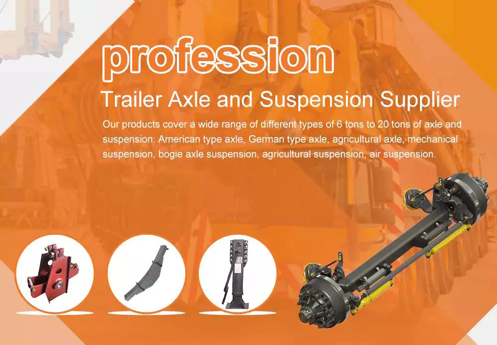
Function
Axle springs are used to support the axle. The spring rate depends on the amount of load applied to the axle. The position of the axle can be determined by detecting signals produced by a position sensor. The sensor detects a change in distance between the axle body and the chassis. The spring rate is then adjusted to provide the required level of deflection.
The differential between the spring supported and unsprung axle suspension can lead to dangerous operating conditions. An operator may not always be aware of the occurrence of a switch from spring-supported to unsprung condition, and may overtax the vehicle as a result. Thus, the proper operation of axles depends on a thorough understanding of axle functions.
The Michigan DOT study used mechanistic models and laboratory studies to develop axle factors. These factors describe the relative damage caused by a single distress to a standard axle. They were used to adjust the AASHTO-based LEFs for single axle weights and to derive new LEFs independent of ESALs.
Models for estimating service lives are based on the work of Timm et al. for the FHWA. These models assume accurate axle loading spectra and a small number of tightly defined scenarios. This greatly simplifies the task of estimating LEFs and improves the accuracy of results.
The MEPDG version of the model supports the NAPCOM and PaveDAT models. They show a considerable variation in the effects of different axle weights on various metrics of pavement condition. This is because different axle weights can cause different results in different sections, if they are associated with two failure mechanisms.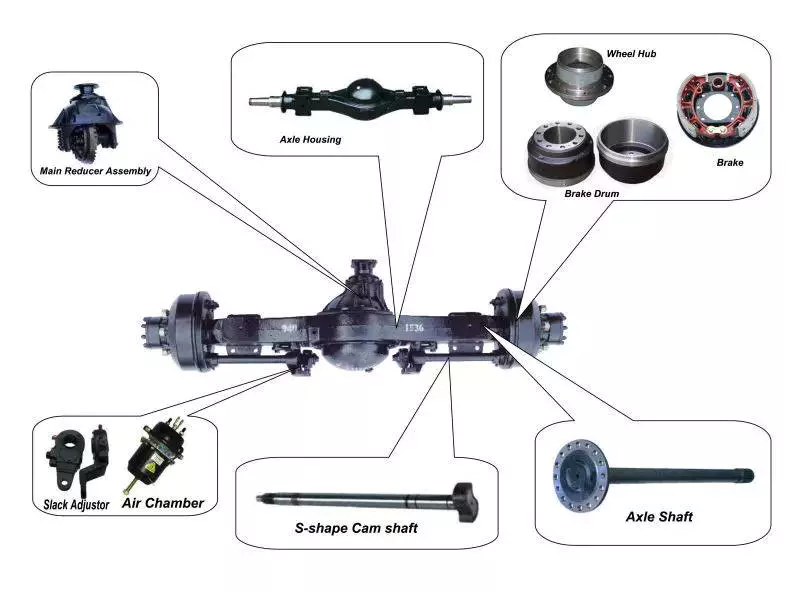
Types
There are many different types of axles, each with their own characteristics. The most common of these is the Ford 9-inch axle, which is found in most Blue Oval muscle cars and trucks. It is so popular that aftermarket companies even make versions for Chevy applications. This particular type of axle features a 3/8-inch square-drive fill plug and is reinforced with a Daytona-style pinion cartridge, which accommodates a stronger pinion head bearing and thicker inner ribbing.
Another type of axle is the rigid front axle, which uses leaf springs to provide suspension. These springs are fixed to spring seats on the axle beam. The axle beam and track rod are connected to each other using screws. The length and thickness of the axle tubes are important for the strength and performance of the axle.
The rear axle is responsible for transferring power to the driving wheels. The front axle, on the other hand, is responsible for processing road shocks and steering. The driving torque produces thrust in the wheels. This force must be transmitted to the chassis frame and body to move the vehicle. These are the most affordable types of axles, but they can also lead to problems.
While many axles are manufactured in standard formats, many of them are custom-made for a particular car, allowing for a more individualized look and performance. In addition to being custom-made for the vehicle, axle housing cases can be either a single unit or split like a banjo. The front opening of the axle housing is closed by a differential carrier, while the rear opening is covered by a spherical cover plate.
Different types of axles have different strengths and weaknesses. Typically, the weight of an axle should be proportionate to the vehicle’s weight and the pressure it will exert on the road. When the axle weight is higher, a vehicle will not be as efficient, as it will use more fuel to move at the same speed. This can cut into profit margins.
Different types of axles can have various purposes, but one main function is to transfer power from the engine to the wheels. These axles need to be durable and able to withstand the weight of a vehicle, as well as withstand accelerated forces.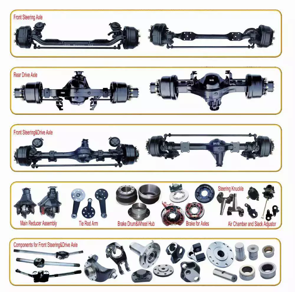
Repair
If you notice any signs of wear or damage to the axle on your vehicle, you may need to repair it. This type of repair will not only protect the wheels, but will also increase the overall performance of your car. A good repair job can help you enjoy smoother driving and better control of your tires. However, there are certain precautions you must take before starting the repair.
To fix an axle, a mechanic must first determine the cause of the problem. This can involve replacing worn or broken parts, replacing them with new ones, and adjusting the car’s alignment. The mechanic will then tighten the fasteners and tires according to manufacturer specifications. Finally, the car will be road tested to ensure that everything is working properly.
A CV joint is also a common item to be replaced. The lubrication in these joints can become dirty, which causes them to wear out. A failing joint will make a clicking sound when it turns sharply. A failed joint may also affect the differential. This part of the car’s drivetrain contains a set of gears that transfer the rotational power of the engine to the wheels. Over time, the gears can wear out, resulting in high labour and replacement costs.
If your car has bent axles, it is important to repair them as soon as possible. Even if the damage is slight, the problem can lead to additional damage to your car’s wheels, CV joints, or other powertrain components. Thankfully, some insurance policies cover the cost of axle repair after an accident.
The average cost to repair an axle varies from about $450 to $900 before taxes. The cost depends on the size of the vehicle and the type of labor required. A rear axle repair can cost up to $700. In addition to labor fees, parts can cost as little as $50 to 70. The cost of the repair can also vary depending on the type of vehicle and the parts used.
If you notice bad vibrations in your vehicle, it’s likely that the axle has been damaged. These vibrations can cause problems with the handling of your vehicle and your comfort while driving.
editor by czh 2022-12-01
China OEM Tapered Roller Front Wheel Hub Unit Bearing Kit for Lada Niva 2121-3103020 713690090 Vkba1324 near me manufacturer
Product Description
Basic information:Pictures:
| Description | Auto bearing VKBA1324 | ||||||||||||||||||||||||||||||||||||||||||||||||||||||||||||||||||||||||||||||||||||||||||||||||||||||||||||||||||||||||||||||||||||||||||||||||||||||||||||||||||||||||||||||||||||||||||||||||||||||||||||||||||||||||||||||||||||||||||||||||||||||||||||||||||||||||||||||||||||||||||
| Material | Chrome steel Gcr15 | ||||||||||||||||||||||||||||||||||||||||||||||||||||||||||||||||||||||||||||||||||||||||||||||||||||||||||||||||||||||||||||||||||||||||||||||||||||||||||||||||||||||||||||||||||||||||||||||||||||||||||||||||||||||||||||||||||||||||||||||||||||||||||||||||||||||||||||||||||||||||||
| Application | For Lada | ||||||||||||||||||||||||||||||||||||||||||||||||||||||||||||||||||||||||||||||||||||||||||||||||||||||||||||||||||||||||||||||||||||||||||||||||||||||||||||||||||||||||||||||||||||||||||||||||||||||||||||||||||||||||||||||||||||||||||||||||||||||||||||||||||||||||||||||||||||||||||
| Size | Single Row Tapered Roller Bearing | ||||||||||||||||||||||||||||||||||||||||||||||||||||||||||||||||||||||||||||||||||||||||||||||||||||||||||||||||||||||||||||||||||||||||||||||||||||||||||||||||||||||||||||||||||||||||||||||||||||||||||||||||||||||||||||||||||||||||||||||||||||||||||||||||||||||||||||||||||||||||||
| Position | Front axle | ||||||||||||||||||||||||||||||||||||||||||||||||||||||||||||||||||||||||||||||||||||||||||||||||||||||||||||||||||||||||||||||||||||||||||||||||||||||||||||||||||||||||||||||||||||||||||||||||||||||||||||||||||||||||||||||||||||||||||||||||||||||||||||||||||||||||||||||||||||||||||
| With ABS | No | ||||||||||||||||||||||||||||||||||||||||||||||||||||||||||||||||||||||||||||||||||||||||||||||||||||||||||||||||||||||||||||||||||||||||||||||||||||||||||||||||||||||||||||||||||||||||||||||||||||||||||||||||||||||||||||||||||||||||||||||||||||||||||||||||||||||||||||||||||||||||||
| Weight | 0.6kg | ||||||||||||||||||||||||||||||||||||||||||||||||||||||||||||||||||||||||||||||||||||||||||||||||||||||||||||||||||||||||||||||||||||||||||||||||||||||||||||||||||||||||||||||||||||||||||||||||||||||||||||||||||||||||||||||||||||||||||||||||||||||||||||||||||||||||||||||||||||||||||
| Brand | SI, PPB, or customized | ||||||||||||||||||||||||||||||||||||||||||||||||||||||||||||||||||||||||||||||||||||||||||||||||||||||||||||||||||||||||||||||||||||||||||||||||||||||||||||||||||||||||||||||||||||||||||||||||||||||||||||||||||||||||||||||||||||||||||||||||||||||||||||||||||||||||||||||||||||||||||
| Packing | Neutral, SI, PPB brand packing or customized | ||||||||||||||||||||||||||||||||||||||||||||||||||||||||||||||||||||||||||||||||||||||||||||||||||||||||||||||||||||||||||||||||||||||||||||||||||||||||||||||||||||||||||||||||||||||||||||||||||||||||||||||||||||||||||||||||||||||||||||||||||||||||||||||||||||||||||||||||||||||||||
| OEM/ODM service | Yes | ||||||||||||||||||||||||||||||||||||||||||||||||||||||||||||||||||||||||||||||||||||||||||||||||||||||||||||||||||||||||||||||||||||||||||||||||||||||||||||||||||||||||||||||||||||||||||||||||||||||||||||||||||||||||||||||||||||||||||||||||||||||||||||||||||||||||||||||||||||||||||
| Manufacture place | ZHangZhoug, China | ||||||||||||||||||||||||||||||||||||||||||||||||||||||||||||||||||||||||||||||||||||||||||||||||||||||||||||||||||||||||||||||||||||||||||||||||||||||||||||||||||||||||||||||||||||||||||||||||||||||||||||||||||||||||||||||||||||||||||||||||||||||||||||||||||||||||||||||||||||||||||
| MOQ | 50 PCS | ||||||||||||||||||||||||||||||||||||||||||||||||||||||||||||||||||||||||||||||||||||||||||||||||||||||||||||||||||||||||||||||||||||||||||||||||||||||||||||||||||||||||||||||||||||||||||||||||||||||||||||||||||||||||||||||||||||||||||||||||||||||||||||||||||||||||||||||||||||||||||
| OEM replacement | Yes | ||||||||||||||||||||||||||||||||||||||||||||||||||||||||||||||||||||||||||||||||||||||||||||||||||||||||||||||||||||||||||||||||||||||||||||||||||||||||||||||||||||||||||||||||||||||||||||||||||||||||||||||||||||||||||||||||||||||||||||||||||||||||||||||||||||||||||||||||||||||||||
| Inspection | 1
Other Ref.: Application: Other types(contact us for more models):
Other Parts: SI&PPB bearing has a plant area of 50,000 square meters, assets of RMB180 million, 500 employees, and 150 professional and technical personnel. The company uses high-quality GCR15 as its raw materials and uses Austenite heat treatment to ensure the service life of the products. Packing: FAQ: Q2:What’s the MOQ? Q3. What are your goods of packing? Q4. What is your sample policy? Q5. Do you have any certificates? Q6:Any warranty of your products.
The Four Basic Components of a Screw ShaftThere are 4 basic components of a screw shaft: the Head, the Thread angle, and the Threaded shank. These components determine the length, shape, and quality of a screw. Understanding how these components work together can make purchasing screws easier. This article will cover these important factors and more. Once you know these, you can select the right type of screw for your project. If you need help choosing the correct type of screw, contact a qualified screw dealer. Thread angleThe angle of a thread on a screw shaft is the difference between the 2 sides of the thread. Threads that are unified have a 60 degree angle. Screws have 2 parts: a major diameter, also known as the screw’s outside diameter, and a minor diameter, or the screw’s root diameter. A screw or nut has a major diameter and a minor diameter. Each has its own angle, but they all have 1 thing in common – the angle of thread is measured perpendicularly to the screw’s axis. HeadThere are 3 types of head for screws: flat, round, and hexagonal. They are used in industrial applications and have a flat outer face and a conical interior. Some varieties have a tamper-resistant pin in the head. These are usually used in the fabrication of bicycle parts. Some are lightweight, and can be easily carried from 1 place to another. This article will explain what each type of head is used for, and how to choose the right 1 for your screw. Threaded shankWood screws are made up of 2 parts: the head and the shank. The shank is not threaded all the way up. It is only partially threaded and contains the drive. This makes them less likely to overheat. Heads on wood screws include Oval, Round, Hex, Modified Truss, and Flat. Some of these are considered the “top” of the screw. PointThere are 3 types of screw heads with points: cone, oval, and half-dog. Each point is designed for a particular application, which determines its shape and tip. For screw applications, cone, oval, and half-dog points are common. Full dog points are not common, and they are available in a limited number of sizes and lengths. According to ASTM standards, point penetration contributes as much as 15% of the total holding power of the screw, but a cone-shaped point may be more preferred in some circumstances. SpacerA spacer is an insulating material that sits between 2 parts and centers the shaft of a screw or other fastener. Spacers come in different sizes and shapes. Some of them are made of Teflon, which is thin and has a low coefficient of friction. Other materials used for spacers include steel, which is durable and works well in many applications. Plastic spacers are available in various thicknesses, ranging from 4.6 to 8 mm. They’re suitable for mounting gears and other items that require less contact surface. NutA nut is a simple device used to secure a screw shaft. The nut is fixed on each end of the screw shaft and rotates along its length. The nut is rotated by a motor, usually a stepper motor, which uses beam coupling to accommodate misalignments in the high-speed movement of the screw. Nuts are used to secure screw shafts to machined parts, and also to mount bearings on adapter sleeves and withdrawal sleeves.
|


